
Receiving apparatus

Inactive Publication Date: 2010-03-25
SONY CORP
View PDF0 Cites 2 Cited by
  • Summary
  • Abstract
  • Description
  • Claims
  • Application Information

AI Technical Summary

Benefits of technology

[0009]Thus, it is desirable to provide a receiving apparatus capable of improving the distortion characteristic readily in a severe radio wave environment.
[0011]According to the embodiment of the present invention, it is possible to secure a more satisfactory reception performance by improving the distortion characteristic even in a severe radio wave environment in the presence of multiple waves.

Problems solved by technology

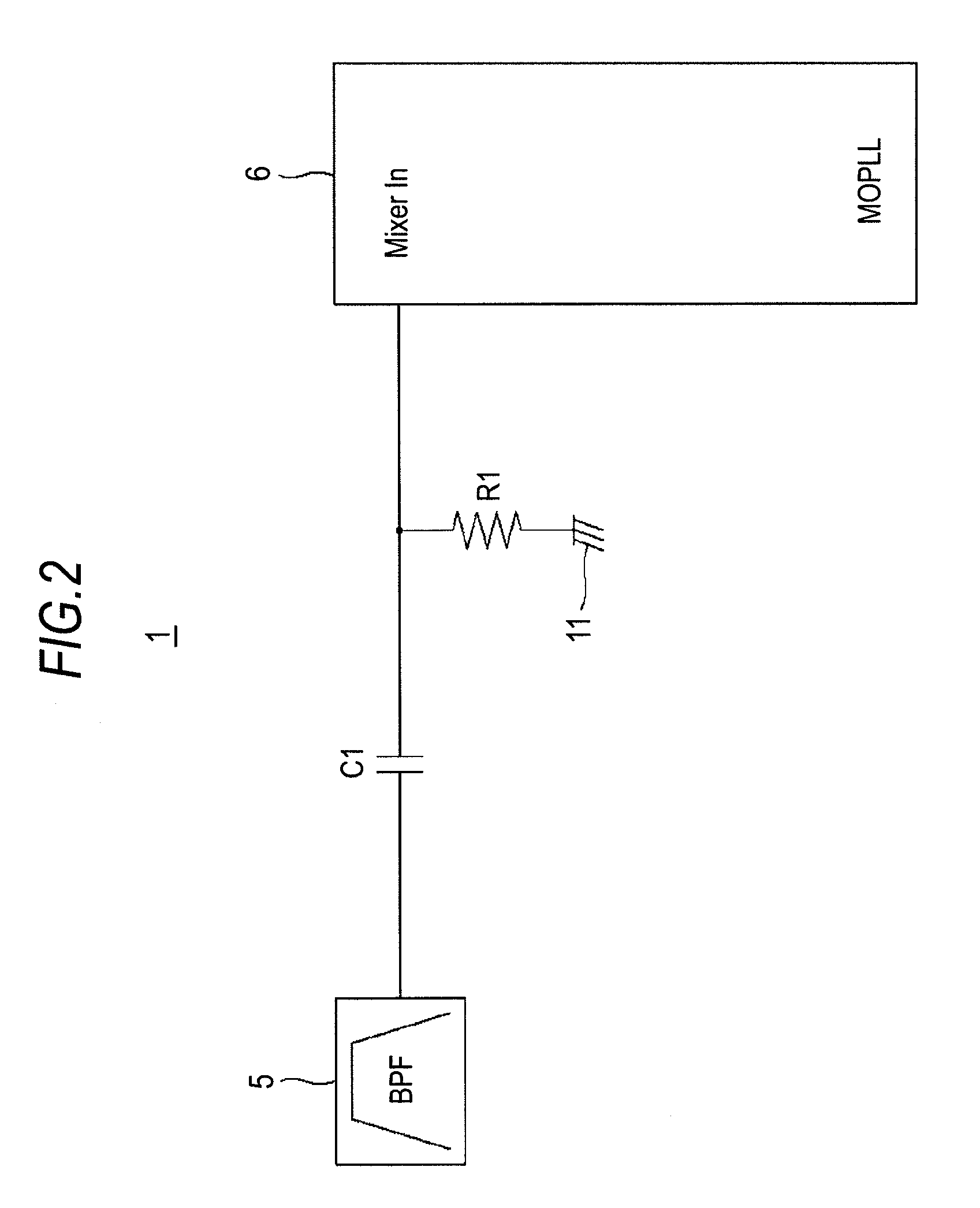
In the frequency band of a radio-frequency signal, however, there is a case where the set value (constant) of the internal reference bias resistor of the MOPLL IC does not take an adequate value.
When the internal bias resistor of the MOPLL IC deviates from the reference value as above, a signal undergoes deformation, which may consequently cause the receiver sensitivity to deteriorate.
Accordingly, in a case where an internal bias voltage of the MOPLL IC is to be manipulated, it is necessary to replace the IC itself and it has been difficult to improve the distortion characteristic.

Method used


Image

  • Receiving apparatus
  • Receiving apparatus
  • Receiving apparatus

Examples


first embodiment

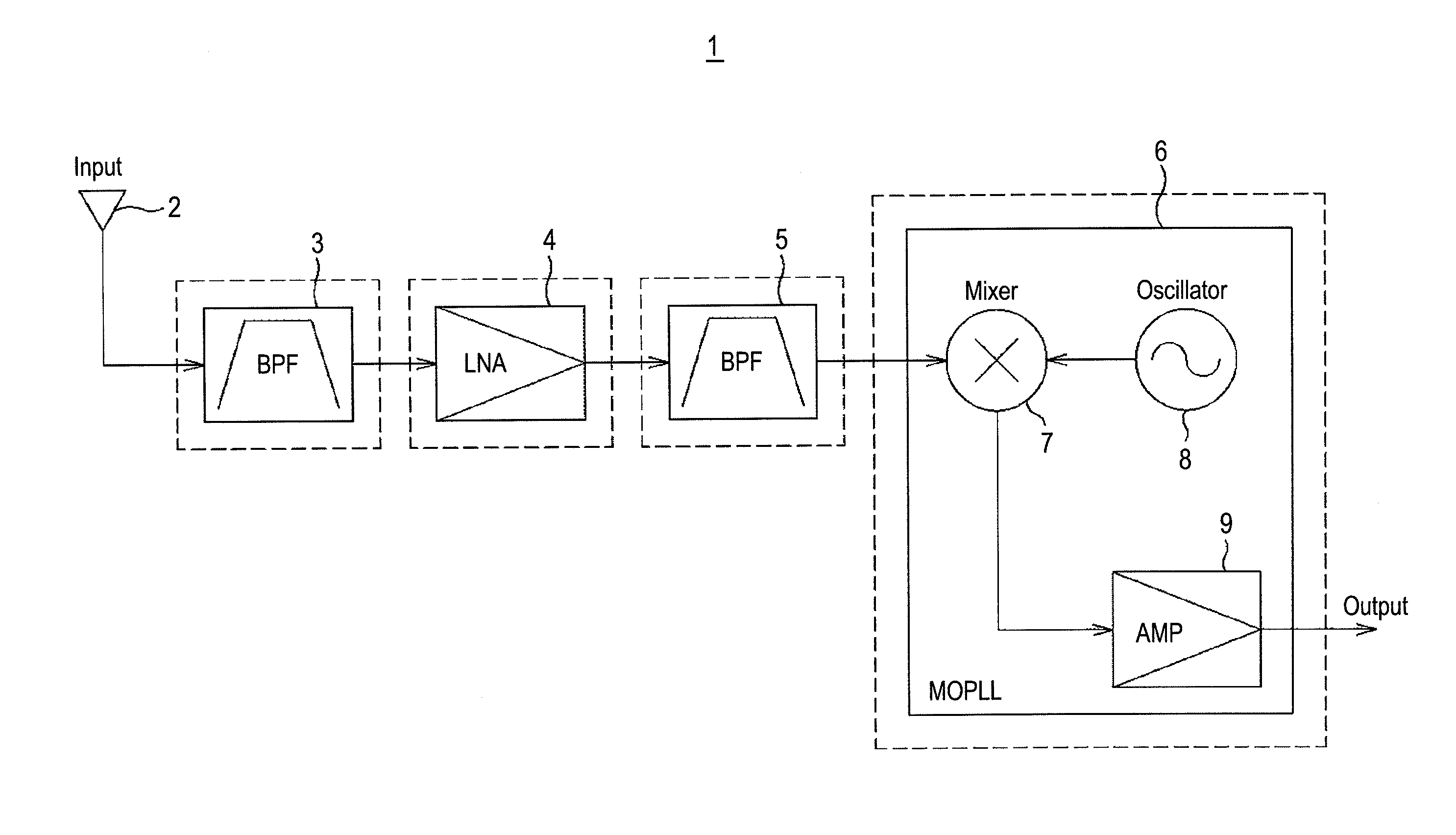
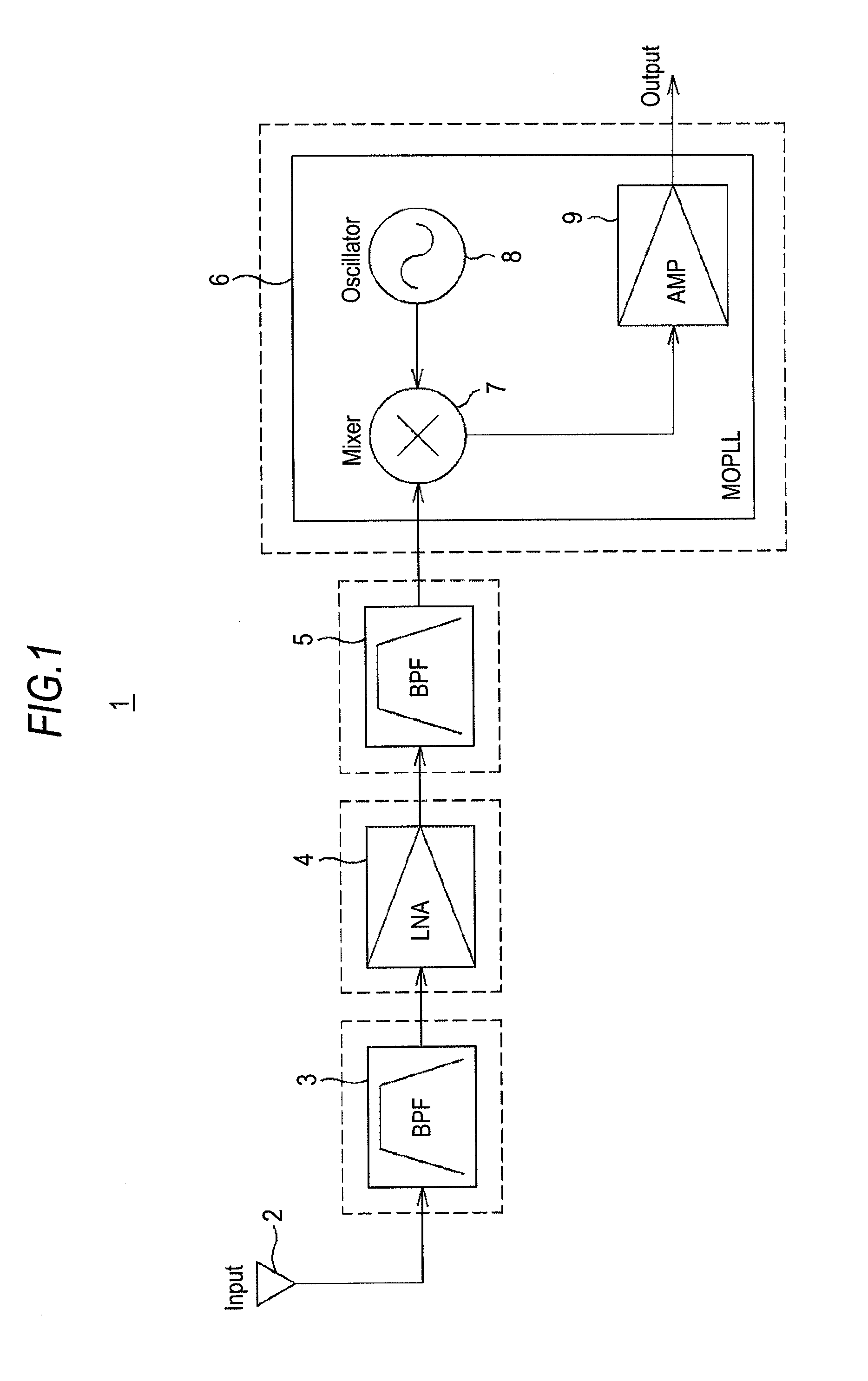
[0019]FIG. 1 is a block diagram showing an example of the configuration of a TV tuner, which is an example of a receiving apparatus according to an embodiment of the present invention. As is shown in FIG. 1, a receiving apparatus 1 includes an antenna 2, a band-pass filter (BPF) 3 in the former stage, a low noise amplifier (LNA) 4 that amplifies a signal, a band-pass filter (BPF) 5 in the latter stage, and an MOPLL IC 6. The MOPLL IC 6 has a mixer 7, a voltage-controlled oscillator 8, and an amplifier 9, and as will be described below, it has capabilities of a mixer, a PLL (Phase Locked Loop) circuit, and an amplifier.

[0020]An example of a reception operation of a radio-frequency signal in the receiving apparatus 1 will now be described. Initially, a radio-frequency signal is inputted into a tuner input terminal (not shown) from the antenna 2. A signal in a reception band (for example, VHF (Very High Frequency) TV broadcasting, UHF (Ultra High Frequency) TV broadcasting, and satelli...

second embodiment

[0034]Hereinafter, a receiving apparatus according to another embodiment of the present invention will be described as a second embodiment. FIG. 5 is a view showing an example of the configuration of a receiving apparatus 20 according to the embodiment of the present invention. To be more concrete, FIG. 5 shows the configuration up to the point where each band of the terrestrial TV broadcasting is inputted into the mixer 7 in the MOPLL IC 6 (up to MIXER IN).

[0035]The receiving apparatus 20 includes a band-pass filter, a capacitor, and a resistor element for each band in the terrestrial TV broadcasting, such as the VHF band and the UHF band. As is shown in FIG. 5, the receiving apparatus 20 includes a band-pass filter 21 that extracts a signal in a frequency band (low VHF), for example, of 90 to 108 MHz, a band-pass filter 22 that extracts a signal in a frequency band (high VHF (high Very High Frequency) of an ultrashort wave (for example, 170 to 222 MHz) higher than the low VHF, and...


PUM


Abstract

A receiving apparatus includes: a frequency conversion portion that has at least a mixer that down-converts a frequency of a reception radio-frequency signal by mixing the radio-frequency signal and an output from a voltage-controlled oscillator and outputs the down-converted radio-frequency signal; and a resistor element that has a resistance value to set a DC bias voltage of an input transistor in the mixer to which the radio-frequency signal is inputted to a center value of a dynamic range.

Description

BACKGROUND OF THE INVENTION[0001]1. Field of the Invention[0002]The present invention relates to a receiving apparatus that improves reception characteristic deterioration of a radio-frequency signal caused by an interfering wave.[0003]2. Description of Related Art[0004]For a distortion characteristic of a receiver, there are a method of changing automatic gain control (AGC) of a low noise amplifier (LNA) most appropriately (see, for example, JP-A-2005-295471) and a method of improving the characteristic of an MOPLL (Mixer Oscillator Phase Locked Loop).[0005]An MOPLL IC is formed, for example, of a mixer, a voltage-controlled oscillator, and an amplifier, and it down-converts a signal (see, for example, JP-2008-53836). To be more concrete, the mixer extracts an intermediate frequency signal (IF signal) from a radio-frequency signal (RF signal) and a locally-generated signal from the voltage-controlled oscillator, that is, it down-converts an RF signal to an IF signal at a lower freq...

Claims


Application Information

Patent Timeline
IPC IPC(8): H03D7/16
CPCH03D1/06
Inventor YOSHIDA, TOSHIKAZU
Owner SONY CORP
Learn More