Safety device

A safe, proximal technology applied in the direction of blood sampling devices, needles, catheters, etc., which can solve the problem of limiting the range of motion of protective components

Inactive Publication Date: 2003-10-22
BECTON DICKINSON & CO
View PDF1 Cites 6 Cited by
  • Summary
  • Abstract
  • Description
  • Claims
  • Application Information

AI Technical Summary

Problems solved by technology

Such prior art guards can be attached to the syringe or needle cannula by a connecting body or an array o

Method used


Image

  • Safety device
  • Safety device
  • Safety device

Examples


Embodiment Construction

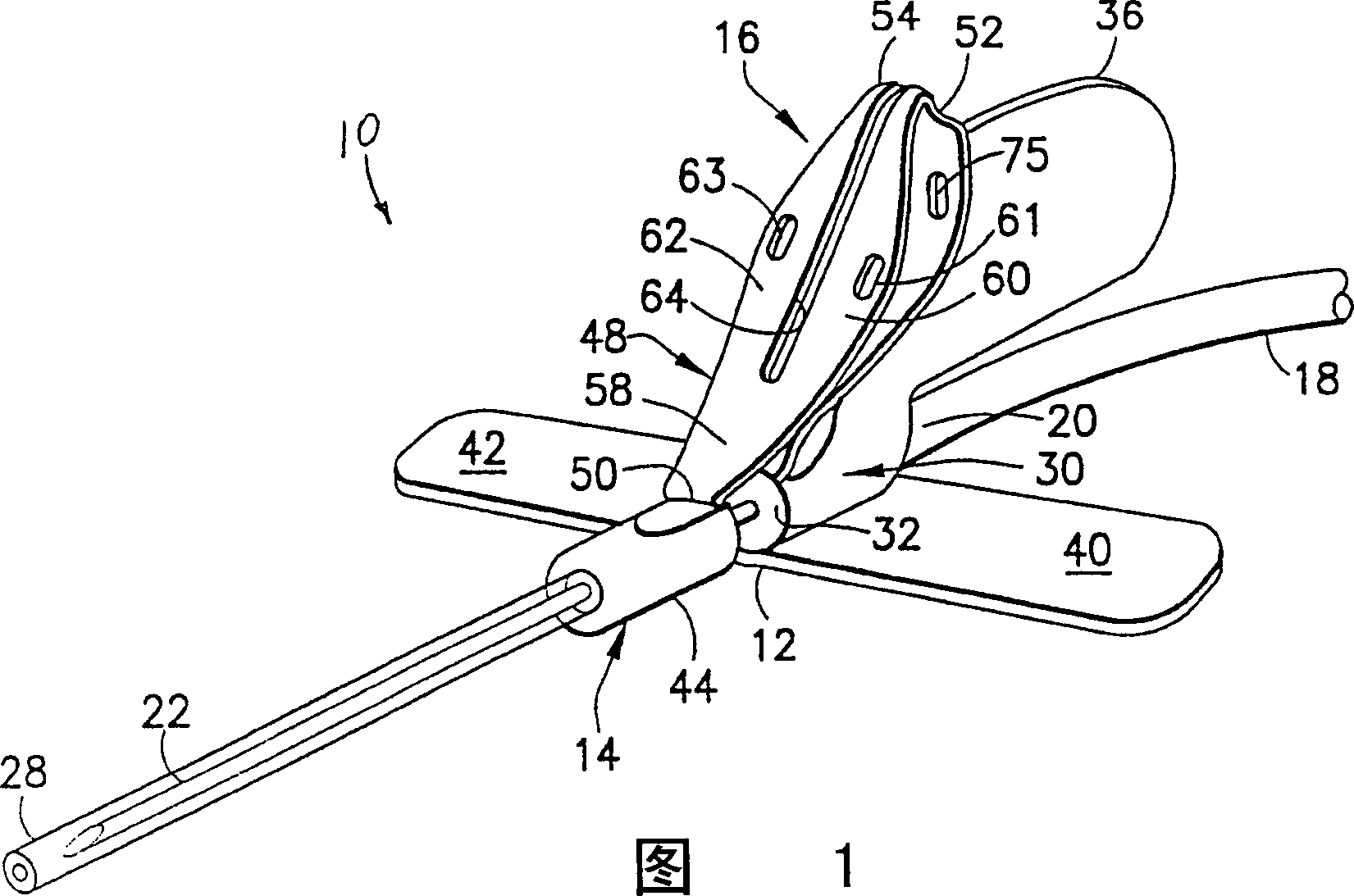
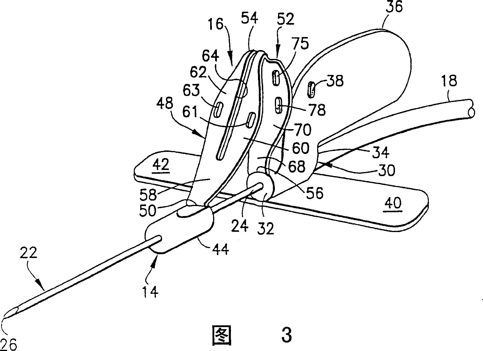
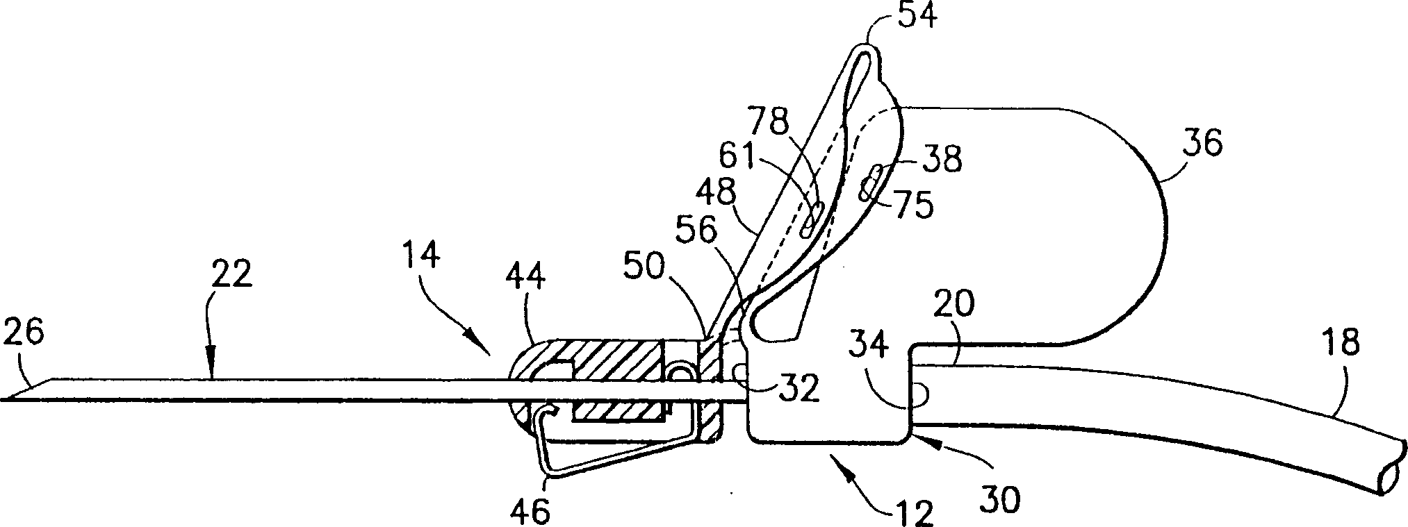
[0024] A wing assembly according to the invention is indicated by reference 10 in FIG. 1 . Wing assembly 10 includes a needle assembly 12 , a shield assembly 14 , a connector 16 and a length of flexible plastic tubing 18 . Plastic tubing 18 has a distal end 20 to which needle assembly 12 is attached, as will be described in more detail below. Plastic tube 18 also includes a proximal end (not shown). The proximal end of the plastic tube 18 can be mounted on a plastic fitting used to connect the wing assembly 10 to the container. In this way, the wing assembly 10 can deliver fluid from the container to the patient or pump fluid from the patient into the container.

[0025] Needle assembly 12 includes a cannula 22 having a proximal end 24 and a distal end 26, the distal end 26 being tapered to form a pointed end, and an inflated lumen between the ends 24,26. Safety cap 28 is passed over needle cannula 22 and is secured by the rest of needle assembly 12 or shield assembly 14 in...


PUM


Abstract

A safety needle assembly has a hub and a needle cannula that projects distally from the hub. A shield is mounted on the needle cannula and can move from a proximal position adjacent the hub and a distal position for shielding the tip of the needle cannula. A fin projects from the hub to facilitate digital manipulation of the needle assembly. A proximal arm is hinged to the hub and a distal arm is hinged to both the proximal arm and the shield. The proximal arm is releasably engaged with the fin when the shield is in the proximal position. However, digital forces on the arms enables the shield to be propelled to the distal position.

Description

[0001] related application [0002] This application claims priority to US Provisional Patent Application No. 60 / 366,702, filed March 21,2002. field of invention [0003] The invention relates to a safety protection component, which is used for hypodermic injection needles, blood collection needles, catheter needles and other medical devices, and can prevent accidental needle sticking injuries. Background technique [0004] Safeguards are widely used in the healthcare industry to eliminate or reduce the risk of accidental needle stick injuries. Safety guards come in many forms, including guards that fit along the needle barrel from a proximal position to a distal position. When the protective part is at the proximal position, the tip of the needle tube is exposed for use. When the guard is in the end position, it covers the tip of the needle guard. [0005] Some shields are large enough to fit over syringes, needle holders, or other medical implements. These larger guard...

Claims


Application Information

Patent Timeline
IPC IPC(8): A61B5/15A61M5/158A61M5/32A61M25/06
CPCA61M5/3275A61M2005/325A61M25/0637A61M25/0625A61M25/0612
Inventor P·布雷斯勒J·D·考勒曼M·蒂尔波
Owner BECTON DICKINSON & CO
Why Eureka
Try Eureka