

Photoswitch and light beam directing assembly
An optical switch and light beam technology, which is applied in the field of optical switches, can solve the problems of reducing the number of channels and reducing the array density of mirrors, etc., and achieve the effects of reducing the trouble of position alignment, suppressing the increase of optical paths, and reducing the reduction of coupling efficiency
- Summary
- Abstract
- Description
- Claims
- Application Information
AI Technical Summary
Problems solved by technology
Method used
Image

Examples
Embodiment Construction
[0045] Hereinafter, embodiments of the present invention will be described with reference to the drawings.
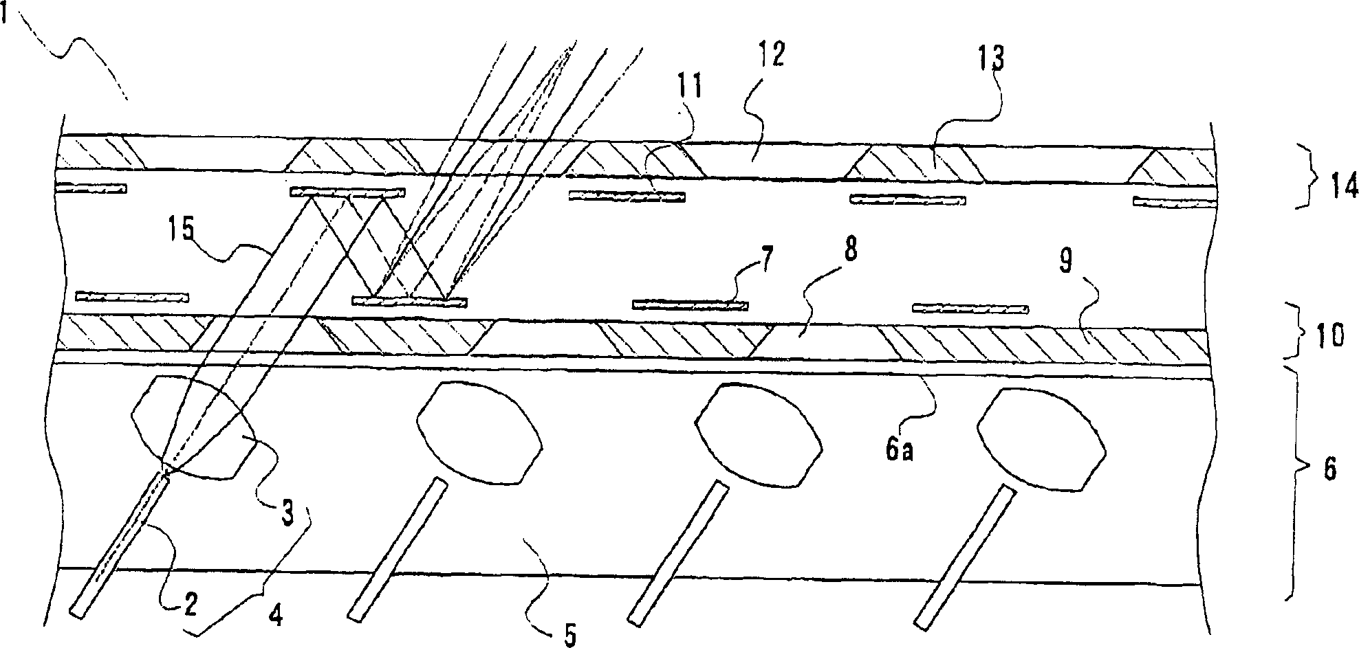
[0046] exist figure 1 Embodiment 1 of the present invention, which shows a cross-sectional view in , is a beam directing unit that has a plurality of optical fibers for input and output of optical signals, and beams the optical signals propagating through each optical fiber, and then advances in arbitrary directions. 1. It has: an optical fiber collimator 4 composed of an optical fiber 2 for propagating optical signals and a collimating lens 3 configured to collimate and beam the optical signal from the optical fiber 2 is arranged on a fiber collimator support 5 And the fiber collimator array 6 that is set; There are a plurality of first mirrors 7 that can control the inclination angle with one rotation axis; Arranging a first reflector array 10 that can pass through a plurality of first windows 8 of light beams; a plurality of second reflectors 11 having a rotation ax...
PUM
 Abstract
Description
Claims
Application Information