Optical fiber coupling member and method for producing same

A technology for optical fiber coupling and optical components, applied in the field of optical fiber coupling components and their manufacturing

Inactive Publication Date: 2015-05-06
KONICA MINOLTA INC
View PDF9 Cites 4 Cited by
  • Summary
  • Abstract
  • Description
  • Claims
  • Application Information

AI Technical Summary

Problems solved by technology

However, in the case of communication using a single-core optical fiber, there is a limit to the capacity, so a means capable of performing data communication exceeding its capacity is required

Method used


Image

  • Optical fiber coupling member and method for producing same
  • Optical fiber coupling member and method for producing same
  • Optical fiber coupling member and method for producing same

Examples


no. 1 approach

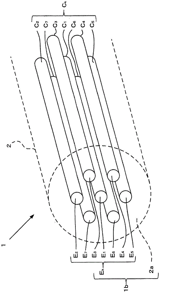
[0055] Next, refer to Figure 2 ~ Figure 4H , the structure and manufacturing method of the coupling member 20 of the first embodiment will be described. The coupling member 20 is arranged between the first optical waveguide and the second optical waveguide. The first optical waveguide is formed by bundling a plurality of one core (optical path) covered with a cladding. The second optical waveguide is composed of a plurality of cores each covered with a cladding. The coupling member 20 optically couples the first optical waveguide and the second optical waveguide. The coupling member 20 in this embodiment couples the optical fiber bundle 10 serving as a first optical waveguide and the multi-core optical fiber 1 serving as a second optical waveguide. figure 2 It is a conceptual diagram showing axial cross-sections of the coupling member 20 , the optical fiber bundle 10 , and the multi-core optical fiber 1 .

[0056] [Structure of Fiber Bundle]

[0057] The optical fiber b...

no. 2 approach

[0108] Next, refer to Figure 5 , the structure of the coupling member 20 of the second embodiment will be described. Figure 5 It is a conceptual diagram showing axial cross-sections of the coupling member 20 , the optical fiber bundle 10 , and the multi-core optical fiber 1 . In this embodiment, an example using a GRIN lens as the first optical system 21 and the second optical system 22 constituting the coupling member 20 will be described. In addition, a detailed description of the same configuration as that of the first embodiment and the like will be omitted.

[0109] [Structure of the coupling part]

[0110] The coupling member 20 in this embodiment has a GRIN lens. A GRIN lens is a lens of a refractive index distribution type that bends diffused light by ion-exchanging the medium constituting the lens to adjust the refractive index distribution inside the lens and concentrates the light. That is, the GRIN lens can adjust the refractive index distribution by ion exch...

no. 3 approach

[0128] Next, refer to Figure 6 , the structure of the coupling member 20 of the third embodiment will be described. Figure 6 It is a conceptual diagram showing axial cross-sections of the coupling member 20 , the optical fiber bundle 10 , and the multi-core optical fiber 1 . In this embodiment, a description is given of using a plurality of optical fibers F as the first optical system 21 constituting the coupling part 20. k , An example in which the GRIN lens SL2 is used as the second optical system 22 . In addition, detailed descriptions of the same configurations and the like as those of the first embodiment and the second embodiment are omitted.

[0129] [Structure of the coupling part]

[0130] The coupling member 20 in this embodiment has the 1st optical system 21 and the 2nd optical system 22 similarly to 1st embodiment and 2nd embodiment.

[0131] In the first optical system 21, as a medium, there are a plurality of optical fibers F k (k=1~n). Fiber F k One end...


PUM


Abstract

Provided is a multi-core fiber coupling member that reduces a decrease in coupling efficiency when a multi-core fiber and a fiber bundle are coupled, as well as a method for producing same. A coupling member has an end on one side in contact with a first optical waveguide formed with a single bundle of a plurality of cores, the bundle being covered with a clad, an end on the other side in contact with a second optical waveguide composed of a plurality of cores each of which is covered with a clad, and a predetermined medium filled between the ends. Respective mode field diameters of light beams caused to enter from the optical paths of the first optical waveguide are changed. Further, intervals of the light beams, whose mode field diameters have been changed, are changed, and the light beams are guided to the cores of the second optical waveguide, respectively.

Description

technical field [0001] The present invention relates to an optical fiber coupling component for coupling optical fibers used in optical communication and the like, and a manufacturing method thereof. Background technique [0002] With the spread of smart phones (smartphones), tablet (tablet PC) terminals, and the like, communication of data having a huge amount of information is required. Along with this, further increase in capacity of optical communication is expected. [0003] Conventional optical communication is performed by using a single-core optical fiber in which one core is provided in a cladding. However, in the case of communication using a single-core optical fiber, there is a limit to the capacity, so a means capable of performing data communication exceeding the capacity is required. [0004] As such data communication means, for example, a multi-core optical fiber is used. A multi-core optical fiber is an optical fiber in which a plurality of cores are pro...

Claims


Application Information

Patent Timeline
Patent Type & Authority Applications(China)
IPC IPC(8): G02B6/32G02B6/04
CPCG02B6/02042G02B6/32G02B6/04G02B6/268
Inventor 今井利幸长井史生
Owner KONICA MINOLTA INC
Why Eureka
Try Eureka