
Photoswitch and light beam directing assembly

An optical switch and beam technology, applied in the field of optical switches, can solve the problems of reducing the number of channels and reducing the arrangement density of mirrors, and achieves the effect of reducing the trouble of position alignment, suppressing the increase of optical paths, and reducing the reduction of coupling efficiency.

Inactive Publication Date: 2006-04-05
HITACHI LTD
View PDF1 Cites 0 Cited by
  • Summary
  • Abstract
  • Description
  • Claims
  • Application Information

AI Technical Summary

Problems solved by technology

In the case of the conventional example of the above-mentioned U.S. Patent No. 6,347,167, since the arrangement density of the mirrors is unfortunately reduced, there is a possibility that the number of channels that can be coupled will be greatly reduced.

Method used


Image

  • Photoswitch and light beam directing assembly
  • Photoswitch and light beam directing assembly
  • Photoswitch and light beam directing assembly

Examples


Embodiment Construction

[0045] Hereinafter, embodiments of the present invention will be described with reference to the drawings.

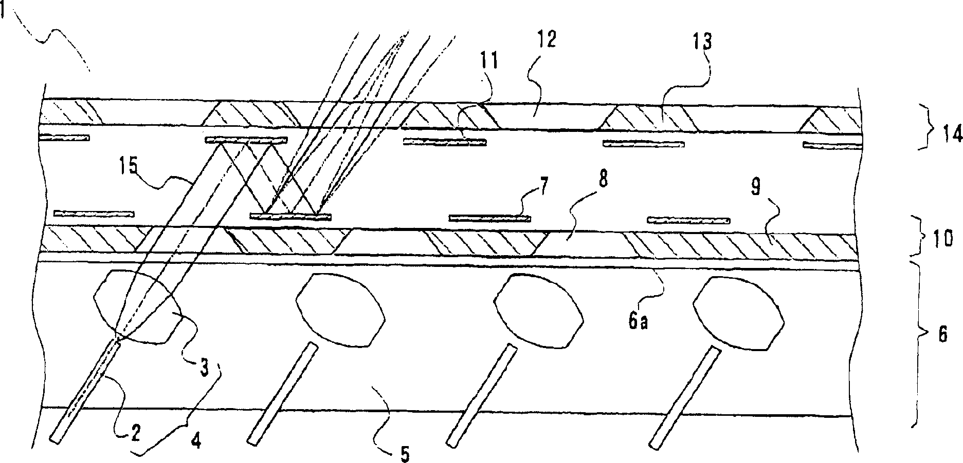
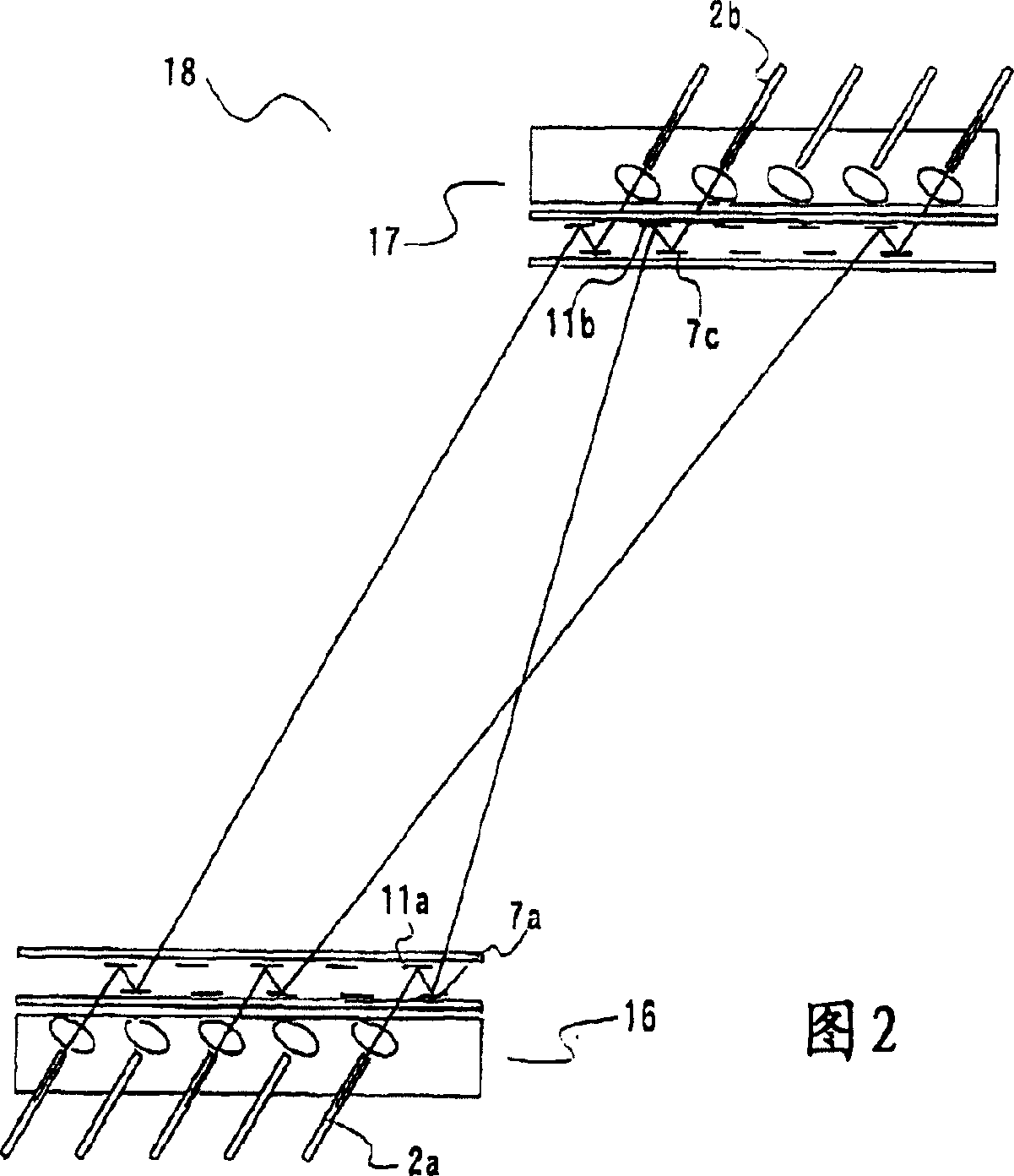
[0046] exist figure 1 Embodiment 1 of the present invention, which shows a cross-sectional view in , is a beam directing unit that has a plurality of optical fibers for input and output of optical signals, and beams the optical signals propagating through each optical fiber, and then advances in arbitrary directions. 1. It has: an optical fiber collimator 4 composed of an optical fiber 2 for propagating optical signals and a collimating lens 3 configured to collimate and beam the optical signal from the optical fiber 2 is arranged on a fiber collimator support 5 And the fiber collimator array 6 that is set; There are a plurality of first mirrors 7 that can control the inclination angle with one rotation axis; Arranging a first reflector array 10 that can pass through a plurality of first windows 8 of light beams; a plurality of second reflectors 11 having a rotation ax...


PUM


Abstract

In a three-dimensional multi-channel optical switch using biaxially movable mirrors, a mirror packing density is improved to support an increased number of channels. The three-dimensional optical switch comprises a fiber collimator array, and a first mirror array and a second mirror array disposed in close proximity to a beam emission surface of the fiber collimator array. The first mirror array has arranged thereon a plurality of first mirrors each having a single rotation axis and a plurality of first windows. The second mirror array has arranged thereon a plurality of second mirrors each having a single rotation axis orthogonal to the first rotation axis and a plurality of second windows. A beam emitted from a fiber collimator passes through the first window, reflects on a fixed mirror and a movable mirror in order, passes through the second window, and exits to the outside.

Description

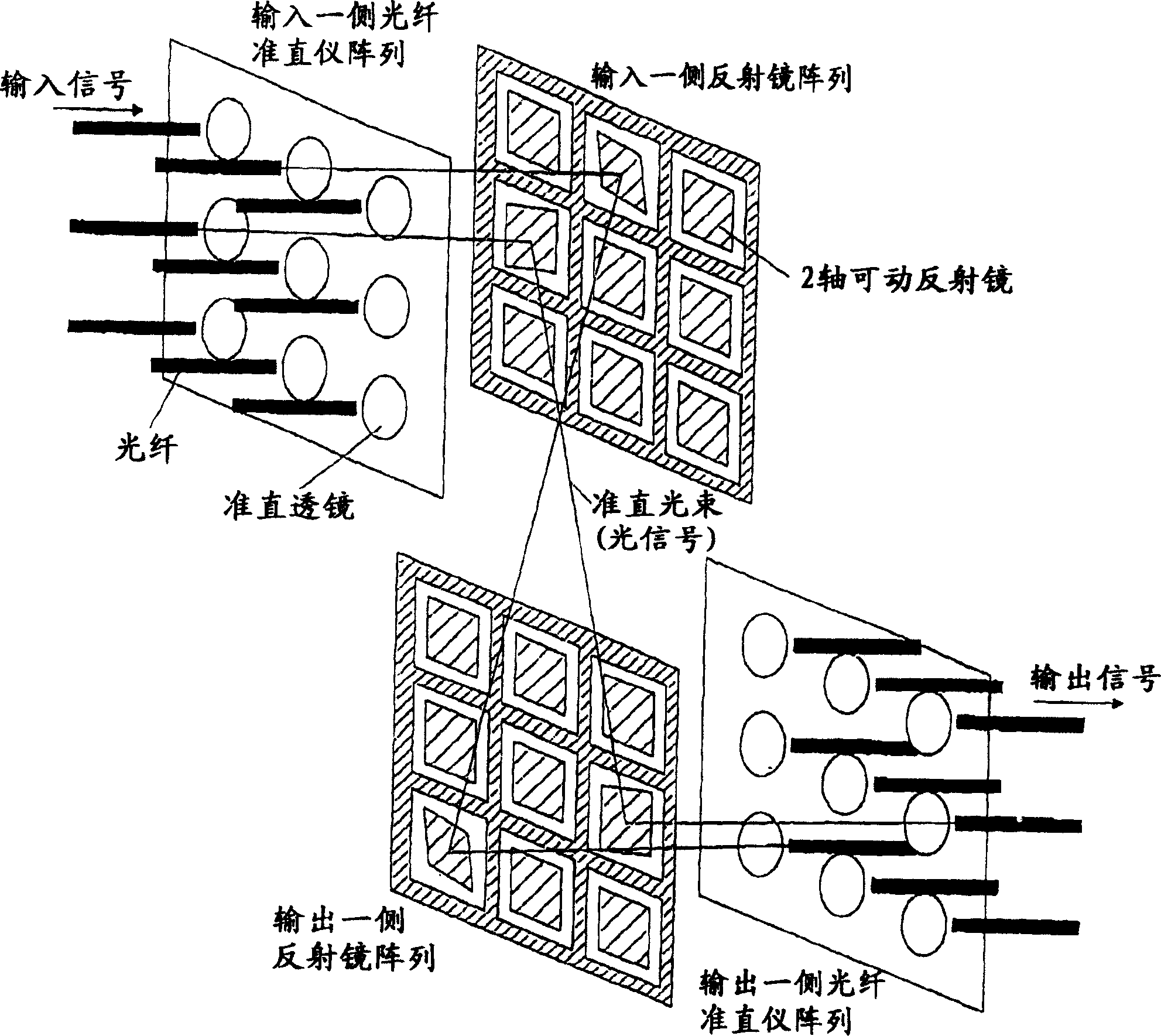
[technical field] [0001] The present invention relates to an optical switch for switching the connection of optical signals transmitted in a plurality of optical fibers, and relates to a three-dimensional optical matrix switch for controlling the direction of beamed optical signals by means of mirrors. [Background technique] [0002] In optical communication using optical fibers, N×N optical switches can be used, that is, any one of the optical signals sent to N input ports through optical fibers can be connected to one of N output ports. , and can switch their connected devices. There has been a report in US Patent No. 6,347,167 on a three-dimensional optical matrix switch that can form an optical path by using an arrayed fiber collimator and mirror array. [0003] In this conventional example, a rack for arranging optical fibers and collimating lenses, a substrate for arranging input-side and output-side micromirrors on the same surface, and a cover for forming a reflecti...

Claims


Application Information

Patent Timeline
Patent Type & Authority Patents(China)
IPC IPC(8): G02B6/35H04B10/12
CPCG02B6/3556G02B6/3512G02B6/357
Inventor 风间敦伊藤康博石川忠明
Owner HITACHI LTD
Learn More