Thermoelectric conversion module

a conversion module and thermoelectric technology, applied in the direction of thermoelectric devices with peltier/seeback effect, basic electric elements, electric apparatus, etc., can solve the problems of low thermoelectric conversion efficiency and high power generation cost, and achieve the effect of increasing the density of the arrangement of the thermoelectric conversion element, increasing the strength of solder-bonding, and increasing the reliability of mounting

Inactive Publication Date: 2013-10-17
PANASONIC INTELLECTUAL PROPERTY MANAGEMENT CO LTD
View PDF5 Cites 6 Cited by
  • Summary
  • Abstract
  • Description
  • Claims
  • Application Information

AI Technical Summary

Benefits of technology

[0030]In the thermoelectric conversion module of the invention, since the width of the wiring that is solder-bonded to the thermoelectric conversion element is appropriately adjusted, a shape of the solder is optimized, and strength of solder-bonding between the thermoelectric conversion element and the electrical wiring plate increases. As a result, mounting reliability increases. In addition, since the width of the wiring that is solder-bonded to the thermoelectric conversion element is appropriately adjusted, arrangement density of the thermoelectric conversion element may be increased.
[0031]More preferably, in the thermoelectric conversion element of the thermoelectric conversion module of the invention, since the thermoelectric conversion material with which the insulating tube is filled, a short-circuit between thermoelectric conversion elements are reliably suppressed. Accordingly, the thermoelectric conversion elements may be arranged in a close contact state, and thus a thermoelectric conversion module in which the thermoelectric conversion elements are arranged with high density may be obtained.

Problems solved by technology

For example, a power generation system using industrial waste heat has been made, but problems such as low thermoelectric conversion efficiency and high power generation cost have been pointed out.

Method used


Image

  • Thermoelectric conversion module
  • Thermoelectric conversion module
  • Thermoelectric conversion module

Examples


Embodiment Construction

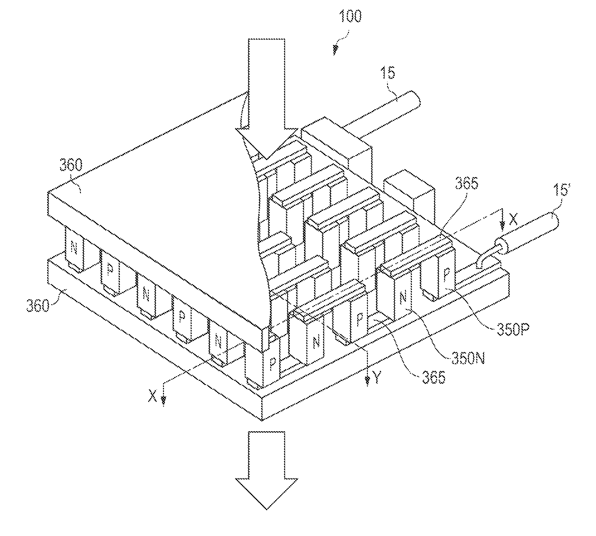
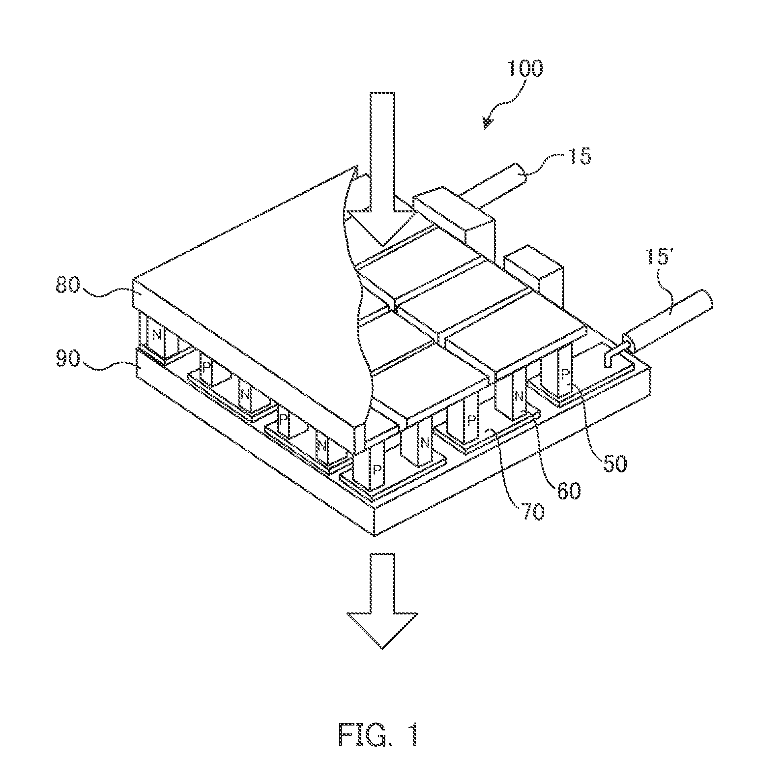
[0041]A thermoelectric conversion module of the invention includes two or more P-type thermoelectric conversion elements, two or more N-type thermoelectric conversion elements, and an electric wiring that connects these in series. The P-type thermoelectric conversion elements and the N-type thermoelectric conversion elements are alternately connected in series by the electrical wiring.

[0042]FIG. 3 illustrates an example of an arrangement state of P-type thermoelectric conversion elements 350P and N-type thermoelectric conversion elements 350N in thermoelectric conversion module 100. It is preferable that P-type thermoelectric conversion elements 350P and N-type thermoelectric conversion elements 350N be disposed in a matrix arrangement. More preferably, P-type thermoelectric conversion elements 350P and N-type thermoelectric conversion elements 350N are arranged along a plurality of rows, and still more preferably three or more rows. Electrical wirings 365 are solder-bonded to both ...


PUM

PropertyMeasurementUnit
outer diameteraaaaaaaaaa
contact angleaaaaaaaaaa

Abstract

An object of the invention is to provide a thermoelectric conversion element and a thermoelectric conversion module in which high-density arrangement is easy, and thus connection reliability is high, and a manufacturing method thereof. There is provided a thermoelectric conversion element including a tube, a thermoelectric conversion material with which the tube is filled, and a plated metal layer that is plated on one end or both ends of the thermoelectric conversion material. The thermoelectric conversion material protrudes from the tube, and the plated metal layer covers a protruding portion of the thermoelectric conversion material. Furthermore, there is provided a thermoelectric conversion module that is obtained by connecting a plurality of thermoelectric conversion elements in series.

Description

CROSS REFERENCE TO RELATED APPLICATIONS[0001]This application is entitled to the benefits of Japanese patent application No. 2012-089940, filed Apr. 11, 2012 and Japanese Patent application No. 2013-043122, filed Mar. 5, 2013, the entire of which are incorporated by reference herein.TECHNICAL FIELD[0002]The present invention relates to a thermoelectric conversion module.BACKGROUND ART[0003]The thermoelectric conversion module includes a P-type thermoelectric element and an N-type thermoelectric conversion element that are connected in series. The thermoelectric element has been developed as a power generation element using a Seebeck effect. For example, a power generation system using industrial waste heat has been made, but problems such as low thermoelectric conversion efficiency and high power generation cost have been pointed out.[0004]An example of a thermoelectric conversion module including the thermoelectric element is shown in FIG. 1 (refer to PTL 1). In thermoelectric conv...

Claims


Application Information

Patent Timeline
Patent Type & Authority Applications(United States)
IPC IPC(8): H01L35/32
CPCH01L35/32H10N10/817H10N10/17
Inventor MAESHIMA, SATOSHITOYODA, KAORIHIGASHIDA, TAKAAKIKUBO, TAKASHI
Owner PANASONIC INTELLECTUAL PROPERTY MANAGEMENT CO LTD
Why Eureka
Try Eureka