
Shape calculation apparatus and method, measurement apparatus, method of manufacturing article, storage medium

a technology of measurement apparatus and shape calculation, applied in the direction of reflective surface testing, instruments, image enhancement, etc., can solve the problems of increasing the cost of the apparatus, small error, and decreasing accuracy resolution, so as to achieve the effect of achieving a general shape and higher accuracy

Inactive Publication Date: 2015-04-30
CANON KK +1
View PDF10 Cites 2 Cited by
  • Summary
  • Abstract
  • Description
  • Claims
  • Application Information

AI Technical Summary

Benefits of technology

The present invention improves the accuracy of overall shape by connecting partial regions while accounting for measurement errors, orientation errors, and system errors.

Problems solved by technology

Upsizing a measurement apparatus to measure the shape of the element increases the measurement dynamic range, thereby decreasing the accuracy resolution and increasing the cost of the apparatus.
In general, in interference measurement or the like, since it is impossible to perform measurement if data itself includes an inclination, the inclination error is very small, and the orientation error can be approximated by linear calculation.
On the other hand, as for measurement data such as measurement data of a three-dimensional shape measurement apparatus for which it is necessary to perform nonlinear calculation such as coordinate rotation to correct the orientation error, if six degrees of freedom of the orientation error are provided to the n partial regions, the number of degrees of freedom to be calculated is sixth power of n. In this case, the calculation amount is enormous, and thus it is difficult to apply the technique to practical measurement.
In each of the above-described literatures, errors included in the result of measuring a partial region are only an orientation error and system error.
That is, the orientation error includes translation / rotation components of the measurement result, and the system error is common to all the measurement results.
However, in actual measurement, the measurement result of each partial region includes various measurement errors in addition to a change in orientation.
For example, if measurement using interference light is performed, the optical path of the interference light changes according to a change in temperature or pressure in a measurement environment, resulting in an error in measurement value.
Also, if the relative distance between the measurement reference and an object to be measured changes due to the temperature deformation of the apparatus structure or the like, an error occurs in measurement value.
Alternatively, when an object to be measured is held on a measurement apparatus, a change in friction force at the holding position or holding point deforms the object to be measured, resulting in an error in measurement value.
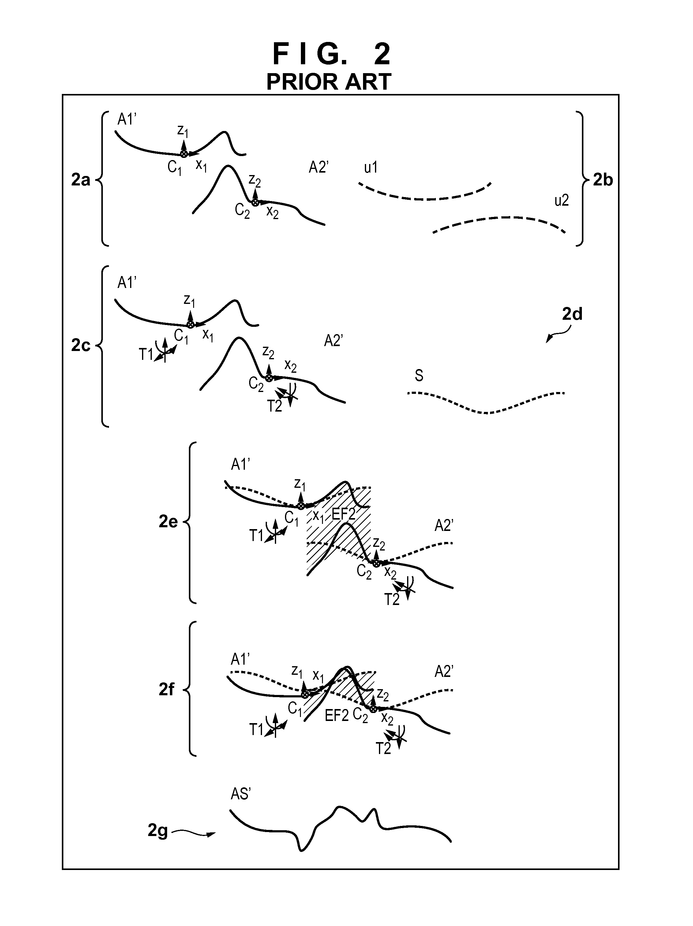
As described above, when performing stitch calculation using the shape data of a partial region whose shape measurement reproducibility is unsatisfactory, the conventional techniques set only the orientation error and system error as calculation parameters.
As a result, when combining the shape data, the discontinuity of the respective shape data in the vicinity of the overlapping regions particularly becomes large.
Along with this, especially at the connection position of the partial regions, a higher-order spatial frequency error such as a step shape or edge shape becomes large.

Method used


Image

  • Shape calculation apparatus and method, measurement apparatus, method of manufacturing article, storage medium
  • Shape calculation apparatus and method, measurement apparatus, method of manufacturing article, storage medium
  • Shape calculation apparatus and method, measurement apparatus, method of manufacturing article, storage medium

Examples


first embodiment

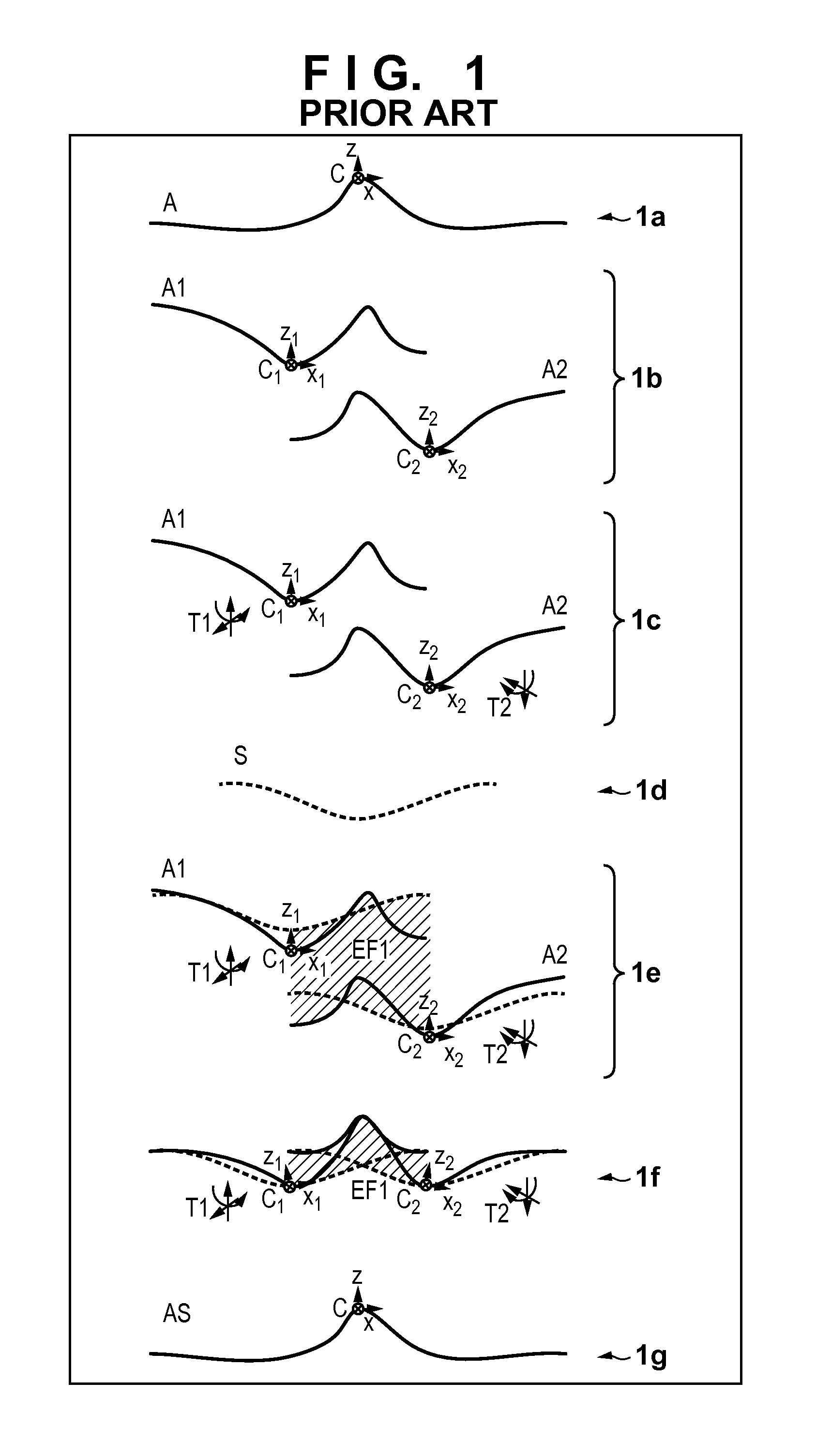
[0033]FIG. 1 shows a conventional stitch technique. FIG. 12 is a flowchart illustrating the conventional stitch technique. The conventional stitch technique is described in, for example, Japanese Patent Laid-Open No. 2004-125768. For the sake of simplicity, when connecting the shape data of two partial regions on a surface to be measured using overlapping measurement regions, especially connection at an arbitrary section in partial measurement data will be explained. Note that it will be understood that there is no difference in essence of the technique even when the shape data of three or more partial regions are connected.

[0034]Referring to FIG. 1, 1a shows the sectional shape of a surface A to be measured of an object to be measured. The surface A to be measured includes coordinates C serving as a reference, and X-, Y-, and Z-axes are defined. A shape measurement apparatus serving as a shape calculation apparatus according to the present invention measures the first partial regio...


PUM


Abstract

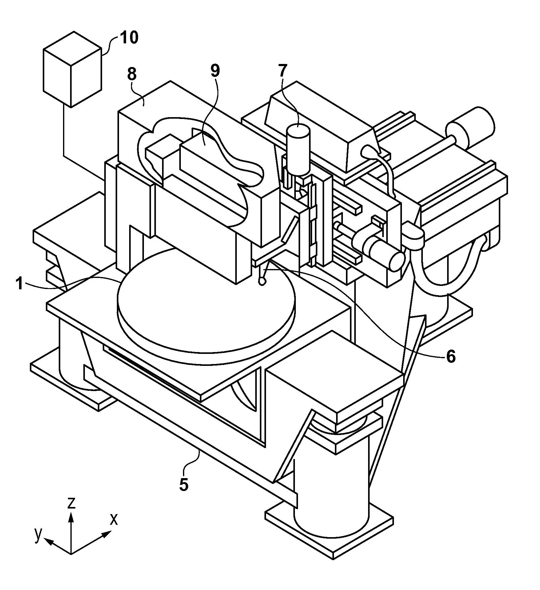
A shape calculation apparatus obtains measurement data of a first shape of a first partial region on a surface to be measured, and obtains measurement data of a second shape of a second partial region partially overlapping the first partial region on the surface to be measured. The apparatus determines a first shape correction parameter and a second correction parameter so that the value of an evaluation function for evaluating shape data obtained by correcting the measurement data of the first and second shapes by the first shape correction parameter and the second correction parameter falls within a tolerance range. The apparatus generates shape data of an entire region including the first and second partial regions by respectively correcting the measurement data of the first and second shapes using the first shape correction parameter and the second correction parameter, and combining the corrected shape data.

Description

BACKGROUND OF THE INVENTION[0001]1. Field of the Invention[0002]The present invention relates to a shape calculation apparatus and method for calculating the shape of a surface to be measured, a measurement apparatus, a method of manufacturing an article, and a storage medium.[0003]2. Description of the Related Art[0004]In astronomy / space observation, the semiconductor industry, or the like, it is increasingly required to upsize an optical element to be used to the order of one to several meters. Upsizing a measurement apparatus to measure the shape of the element increases the measurement dynamic range, thereby decreasing the accuracy resolution and increasing the cost of the apparatus. To solve this problem, so-called stitch measurement is generally performed to obtain the overall shape by measuring the shapes of a plurality of partial regions of an object to be measured, and combining the shape data of the plurality of partial regions.[0005]Japanese Patent Laid-Open No. 2004-1257...

Claims


Application Information

Patent Timeline
Patent Type & Authority Applications(United States)
IPC IPC(8): G01B21/20
CPCG01B21/20G01B11/2441G01B2210/52G01M11/005G06T2207/10028G06T2207/30148G06T7/33
Inventor OOTA, TETSUJINEGISHI, MAHITOYAMASHITA, TAKUYA
Owner CANON KK
Learn More