Fin stabilized projectile and loading components

a stabilized and projectile technology, applied in the field of projectiles, can solve the problems of barrel heat up and projectile parts to be cold formed

Inactive Publication Date: 2020-10-01
AUSKUR FIREARMS & MUNITIONS INC
View PDF0 Cites 0 Cited by
  • Summary
  • Abstract
  • Description
  • Claims
  • Application Information

AI Technical Summary

Benefits of technology

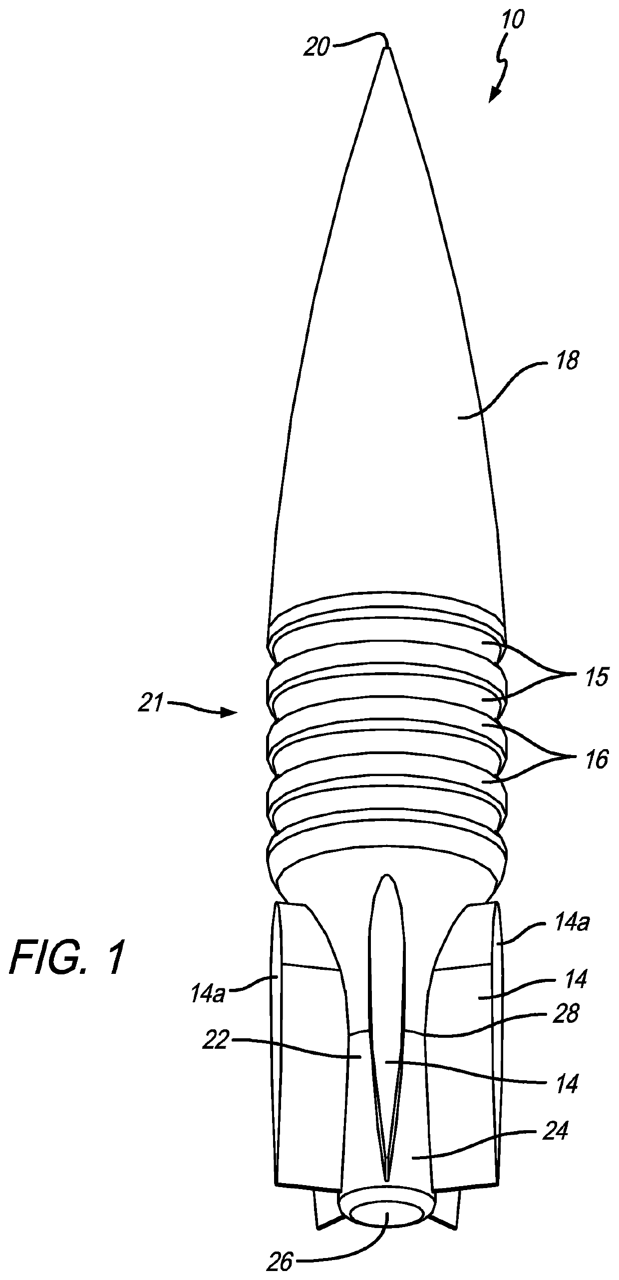
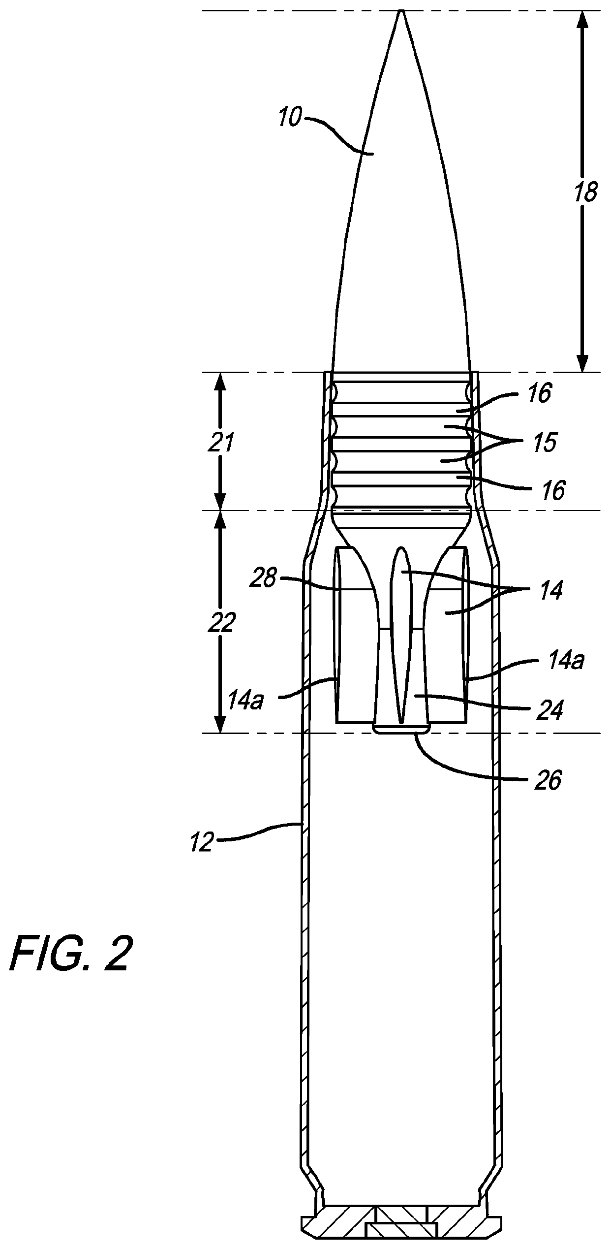
[0034]Referring now to the drawings, which are for purposes of illustrating the present invention and not for purposes of limiting the same, the figures show various embodiments of bullets or projectiles. FIGS. 1 and 2 show a bullet or projectile 10 that can be loaded into a casing 12 and fired from a standard rifle. In a preferred embodiment, the projectile 10 includes a plurality of fins 14 and a plurality of annular grooves or rings 15 and alternating ridges 16. When traveling down the barrel of a gun, the grooves 15 help form the necessary seal and the fins 14 provide stabilization of the projectile 10 as it travels through the air to the target. It will be appreciated by those of ordinary skill in the art that instead of using a continuous large amount of body to form the seal (as is the case with a standard bullet), the grooves 15 reduce the amount of projectile body or surface area to form the seal.
[0037]It will be appreciated that the geometry and shapes of both the projectile and the jacket may change based on calibers and projectile weights. Fin shape and mass can be modified to move the CG (center of gravity) and increase or decrease rotation and stability in projectile flight. Generally, the system allows the overall shape of the projectile envelope flexibility not achievable in traditional projectiles.
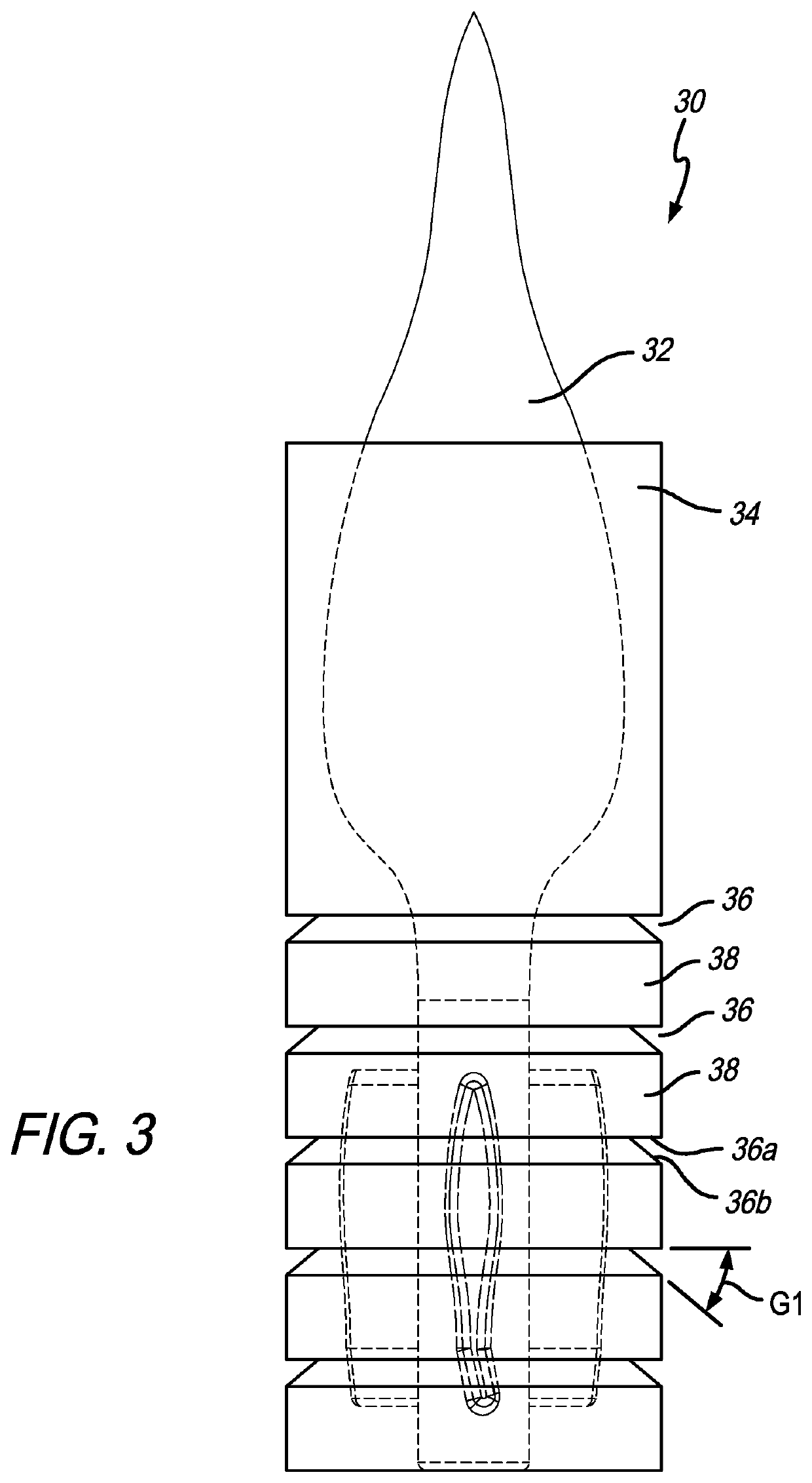
[0050]It will be appreciated that the covered projectile 30 provides lower friction and drag compared to the prior art, which results in lowered friction heating and reduced barrel wear. The fins provide stabilization in flight. A rudder may be included in the fin to augment rotation in flight. The body of the projectile is formed to lower drag in flight and increase airflow in the fin area. As a result, the inventor has found that speed is increased and velocity degradation is reduced. In an exemplary embodiment, the projectile is made of copper, however, any metal or material is within the scope of the invention.

Problems solved by technology

As the projectile travels down the barrel a high amount of chamber pressure and friction causes portions of the projectile to be cold formed.
This causes the barrel to heat up.

Method used


Image

  • Fin stabilized projectile and loading components
  • Fin stabilized projectile and loading components
  • Fin stabilized projectile and loading components

Examples


Embodiment Construction

[0005]In accordance with a first aspect of the present invention there is provided a covered projectile that includes a projectile having a nose portion, a middle portion, a rear portion, and a plurality of fins extending outwardly from the rear portion, and a jacket that surrounds at least a portion of the projectile and includes an exterior surface and an interior surface. The jacket includes a front cone. A plurality of annular grooves are defined in the exterior surface of the jacket. In a preferred embodiment, the middle portion has a greater diameter than the nose portion and the rear portion. Preferably, the projectile defines a projectile axis, each fin includes a front portion that defines a front portion axis and a tail portion that defines a tail portion axis. The front portion axis of each fin extends parallel to the projectile axis, and the tail portion axis of each fin defines an acute angle with the front portion axis.

[0006]In a preferred embodiment, the interior surf...


PUM


Abstract

A covered projectile that includes a projectile having a nose portion, a middle portion, a rear portion, and a plurality of fins extending outwardly from the rear portion, and a jacket that surrounds at least a portion of the projectile and includes an exterior surface and an interior surface. The jacket includes a front cone. A plurality of annular grooves are defined in the exterior surface of the jacket.

Description

CROSS REFERENCE TO RELATED APPLICATIONS[0001]This application claims the benefit of U.S. Provisional Application No. 62 / 671,334, filed May 14, 2018, the entirety of which is incorporated by reference herein.FIELD OF THE INVENTION[0002]The present invention relates generally to a projectile, and more particularly to a projectile that includes stabilization fins and for the components for loading the projectile into a cartridge.BACKGROUND OF THE INVENTION[0003]Standard bullets, projectiles or rounds are cylindrical, pointed objects that are fired from a barrel with rifling therein. The rifling in the bore instills spin and, therefore, stability in the projectile as it travels to its target. As the projectile travels down the barrel a high amount of chamber pressure and friction causes portions of the projectile to be cold formed. This causes the barrel to heat up. The present invention helps solve this problem.[0004]SUMMARY OF THE PREFERRED EMBODIMENTS[0005]In accordance with a first ...

Claims


Application Information

Patent Timeline
Patent Type & Authority Applications(United States)
IPC IPC(8): F42B10/06F42B5/02
CPCF42B5/02F42B10/06F42B10/46F42B14/064F42B33/005
Inventor BERGER, LEO
Owner AUSKUR FIREARMS & MUNITIONS INC
Why Eureka
Try Eureka