Permanent magnet for motor

A technology of permanent magnets and motors, which is applied in the direction of permanent magnets, inorganic material magnetism, and static parts of magnetic circuits, etc., and can solve problems such as insufficient magnetic field and small torque

Inactive Publication Date: 2003-10-29
TODA IND
View PDF0 Cites 6 Cited by
  • Summary
  • Abstract
  • Description
  • Claims
  • Application Information

AI Technical Summary

Problems solved by technology

[0003] However, if Figure 14 (B), Figure 15 As shown in (B), in general, when the length of the magnet 21 is compared with the length of the rotor 23 facing it, the length of the magnet 21 is large, and the surface magnetic fields of the two end regio

Method used


Image

  • Permanent magnet for motor
  • Permanent magnet for motor
  • Permanent magnet for motor

Examples


Embodiment 1

[0082] Example 1, Comparative Examples 1-2

[0083] Using the above-mentioned ratio and forming conditions, a ring-shaped motor magnet is manufactured, and the magnet is used as a stator to assemble as Picture 10 or Figure 8 The performance of the motor shown (gap between stator and rotor = 0.2 mm) was evaluated. The results are shown in Table 1. As can be seen from Table 1, Example 1 is 1.1 times the gap magnetic field of Comparative Example 1. In addition, since the L2 / L1 of Comparative Example 2 is small, the gap magnetic field is 0.9 times that of Comparative Example 1.

[0084] In addition, for Comparative Examples 1 to 2, in Picture 10 (B), such as Figure 14 As shown, an annular magnet oriented parallel to the active surface from the non-acting surface is used.

[0085] Example 1

[0086] *in Picture 10 (B), such as Figure 14 As shown, the active surface is oriented parallel from the non-active surface.

Embodiment 2~3

[0088] Except for the changes shown in Table 2, the same operations as in Example 1 were performed. The results are shown in Table 2. For comparison, the results of Example 1 are also listed in Table 2. As can be seen from Table 2, Examples 2 to 3 increase to 1.06 times and 1.15 times of the gap magnetic field of the aforementioned Comparative Example 1.

[0089] Example 1

Embodiment 4~6、 comparative example 3

[0091] Except for the changes shown in Table 3, the same operations as in Example 1 were performed. The results are shown in Table 3. As can be seen from Table 3, in Examples 4 to 6, the gap magnetic field increases to 1.07 times, 1.04 times, and 1.10 times that of Comparative Example 3.

[0092] In addition, for Comparative Example 3, Figure 8 (B), such as Figure 14 As shown, a tile-shaped magnet oriented parallel to the active surface from the non-active surface is used.

[0093] Example 4

[0094] *in Figure 8 In, such as Figure 14 As shown, the active surface is oriented parallel from the non-active surface.


PUM

PropertyMeasurementUnit
The average particle sizeaaaaaaaaaa

Abstract

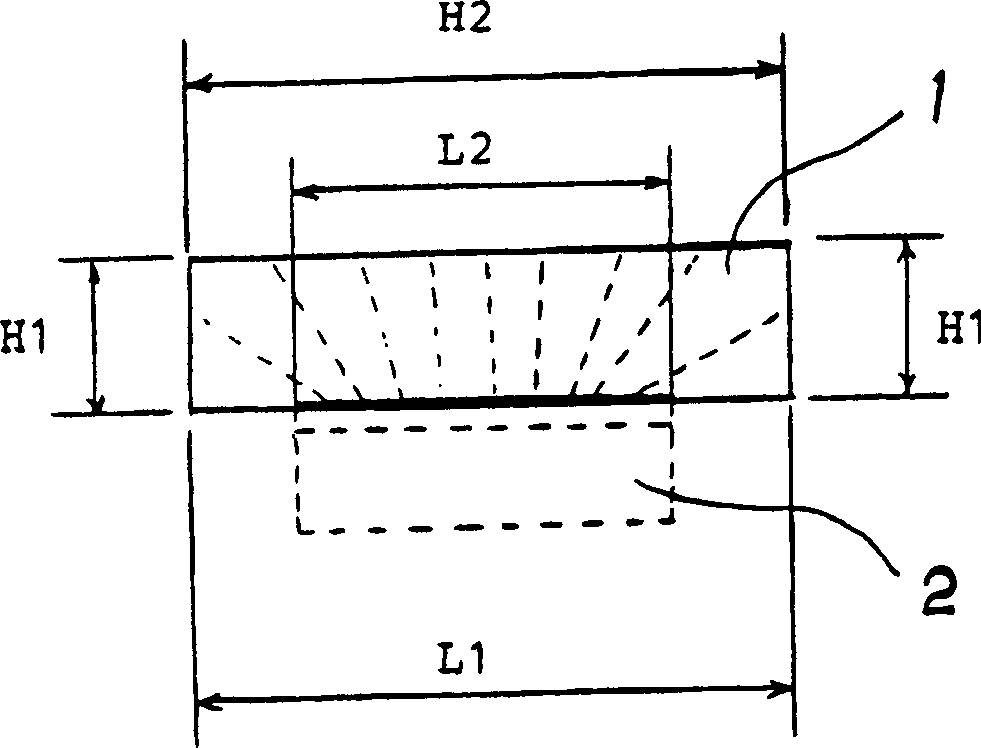
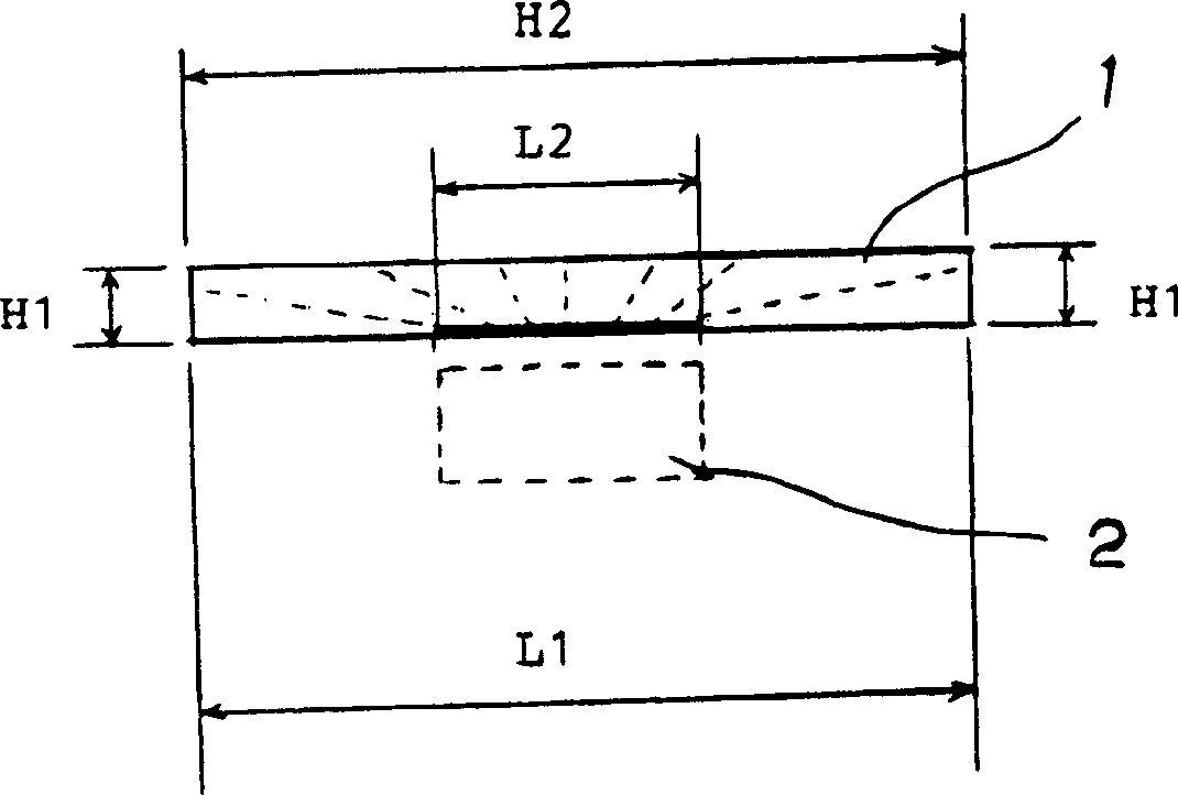
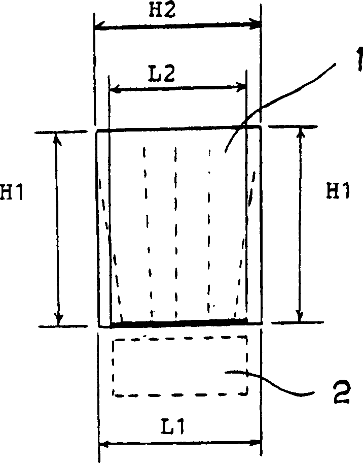
Provided is a permanent magnet that effectively utilizes a magnetic field and improves motor torque. In the cross-section in the longitudinal direction, one of the front and the back is used as the action surface L1, and the action area L2 narrower than the action surface L1 is provided in the action surface L1, and the action area L2 that is in contact with the aforementioned action surface L1 is provided. The non-active surface H1 on both sides of the permanent magnet and the non-active surface H2 that is in contact with the two side surfaces H1 and is located on the opposite side of the active surface L1. The characteristic of this permanent magnet is that the magnetic powder particles constituting the magnet are easily magnetized. In essence, the orientation is convergent from the non-active surfaces H1 and H2 to the active area L2, and the length relationship between the length of the non-active surface H1 and the length of the active surface L1 satisfies 1/10≤H1/L1≤10/10, while the length of the active area L2 and The length relationship of the acting surface L1 satisfies 35/100≤L2/L1≤98/100.

Description

Technical field [0001] The present invention relates to a permanent magnet for a motor (hereinafter sometimes referred to simply as a magnet). More specifically, it relates to a magnetic field that leaks less from the acting surface of the magnet, uses the magnetic field efficiently, and can increase the torque of the motor. Magnets for motors. Background technique [0002] In the prior art, as such a magnet, for example, such as Figure 14 As shown in (A), on the cross section in the longitudinal direction, a sector magnet oriented in parallel from the non-acting surface H to the acting surface L, and Figure 15 The sector magnet shown in (A) is oriented from the non-acting surfaces H1, H2 to the acting surface L and toward the central area. [0003] But like Figure 14 (B), Figure 15 As shown in (B), generally, when the length of the magnet 21 is compared with the length of the rotor 23 facing it, the length of the magnet 21 is large, and the surface magnetic fields of the two...

Claims


Application Information

Patent Timeline
IPC IPC(8): H01F1/08H01F7/02H02K1/02H02K1/06H02K1/17H02K1/27H02K15/03
Inventor 中塚哲田中逸郎
Owner TODA IND
Why Eureka
Try Eureka