Weft knitting machine with transfer mechanism and transferring method

A technology of loop transfer and flat knitting, applied to flat knitting machines with individual moving needles, textiles and papermaking, weft knitting, etc.

Inactive Publication Date: 2003-11-05
SHIMA SEIKI MFG LTD
View PDF0 Cites 2 Cited by
  • Summary
  • Abstract
  • Description
  • Claims
  • Application Information

AI Technical Summary

Problems solved by technology

[0005] However, as in Figure 5 C with Figure 5 In D, when the TRJ retreats, the coil 105 tends to pull the retreating TRJ103, in this case, as Figure 5 In E, when the knitting needle 101 retreats, the hook 101a may fail to catch the loop 105, resulting in a detached loop 105a

Method used


Image

  • Weft knitting machine with transfer mechanism and transferring method
  • Weft knitting machine with transfer mechanism and transferring method
  • Weft knitting machine with transfer mechanism and transferring method

Examples


Embodiment Construction

[0014] Below, the flat knitting machine with the stitch transfer mechanism and the suitability of the stitch transfer method of the present invention will be described with reference to the accompanying drawings.

[0015] Example.

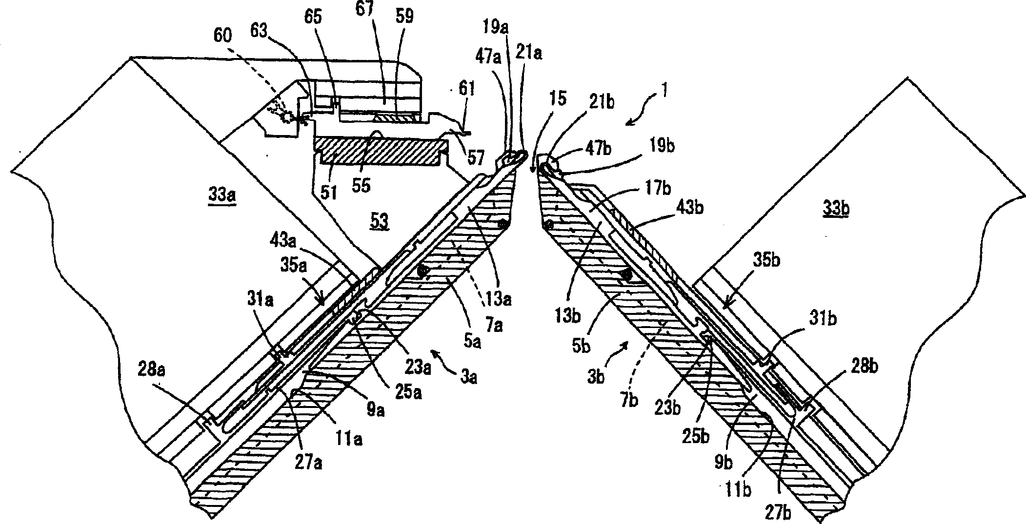
[0016] figure 1 It shows the longitudinal section of the flat knitting machine. The flat knitting machine 1 has a pair of front and rear needle beds 3a, 3b facing each other. In the needle beds 3a, 3b, the needle plates 9a, 9b are erected in the grooves 7a, 7b formed on the base plates 5a, 5b, and the needle grooves 11a, 11b are formed between the adjacent needle plates. The knitting needles 13a, 13b are housed in the inner relative tooth gap 15 so as to be able to advance and retreat. The rear needle bed 3b is configured to be displaceable in the longitudinal direction of the needle bed by a driving device not shown in the figure.

[0017] In this embodiment, the compound needle 13 is installed in the needle groove 11, and the needle body 17 ...


PUM


Abstract

The present invention is to make the hooks (21a, 21b) of the knitting needles (13a, 13b) enter the stitches combined with the transfer foot piece (57) After (88), make the loop transfer base piece enter and push the coil into the advance and retreat track of the hook of the knitting needle, and make the slider (19a, 19b) enter and lock the hook, and the coil is limited in the hook; This prevents the stitches from falling apart and ensures the handover of the stitches from the transfer foot piece to the knitting needle.

Description

technical field [0001] The present invention relates to a TRJ bed with a plurality of rows of transfer base pieces (hereinafter referred to as TRJ) with stitch joints at the front end provided on the upper position of the needle bed, and can be used on the TRJ of the TRJ bed and the knitting needles of the needle bed. A flat knitting machine with a stitch transfer mechanism and a stitch transfer method that transfer stitches between turns. Background technique [0002] The existing flat knitting machine has a pair of front and rear needle beds, and the needle beds can be freely advanced and retreated in the groove formed above, and it is configured that at least one needle bed can move left and right relative to the other needle bed; The needle bed has a TRJ bed in which the TRJ can be freely advanced and retreated in the groove formed on it. In such a flat knitting machine, stitches can be transferred not only between the knitting needles of the front and rear needle beds ...

Claims


Application Information

Patent Timeline
Patent Type & Authority Applications(China)
IPC IPC(8): D04B7/28D04B15/02
CPCD04B7/28D04B15/02D04B7/00
Inventor 涩田武一
Owner SHIMA SEIKI MFG LTD
Why Eureka
Try Eureka