High-wear-resistance highway milling machine tool bit and manufacturing process thereof

A manufacturing process and a technology for a milling machine, which are applied to the high wear-resistant highway milling machine cutter head and its manufacturing process, can solve the problems of different wear progress, increased use costs, wasted time, etc., so as to improve service life and save time. cost, improve wear resistance

Inactive Publication Date: 2020-02-21
马鞍山市世全截齿制造有限公司
View PDF6 Cites 1 Cited by
  • Summary
  • Abstract
  • Description
  • Claims
  • Application Information

AI Technical Summary

Problems solved by technology

However, the knife body is still made of ordinary material, which leads to the fact that the knife body is almost worn out when the tip of the knife is not completely worn. The wear progress of the two is not the

Method used


Image

  • High-wear-resistance highway milling machine tool bit and manufacturing process thereof
  • High-wear-resistance highway milling machine tool bit and manufacturing process thereof
  • High-wear-resistance highway milling machine tool bit and manufacturing process thereof

Examples


Embodiment 1

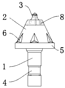
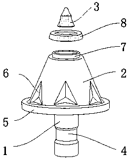
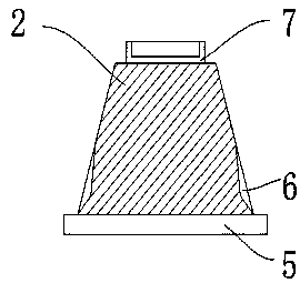
[0028] A high wear-resistant road milling machine cutter head, the overall cutter head is composed of a handle 1 and a blade body 2, the bottom surface of the handle 1 is provided with an arc-shaped installation groove 4, and the blade body 2 is installed on the top of the handle 1 , and a chassis 5 is provided between the blade body 2 and the handle 1, and the chassis 5 is located on the lower surface of the blade body 2, and several heat dissipation guide grooves 6 are provided at the bottom surface of the blade body 2, and the upper surface of the blade body 2 is fixedly connected with Install the ring 7, the outer surface of the installation ring 7 is welded with a wear-resistant ring 8, and the inwall of the installation ring 7 is welded with an alloy tip 3; its manufacturing process is as follows:

[0029] S1. Casting molding: pour molten iron into the molding mold, then cool it down to room temperature naturally, and demould to form the blank of the cutter head;

[0030...

Embodiment 2

[0036] A high wear-resistant road milling machine cutter head, the overall cutter head is composed of a handle 1 and a blade body 2, the bottom surface of the handle 1 is provided with an arc-shaped installation groove 4, and the blade body 2 is installed on the top of the handle 1 , and a chassis 5 is provided between the blade body 2 and the handle 1, and the chassis 5 is located on the lower surface of the blade body 2, and several heat dissipation guide grooves 6 are provided at the bottom surface of the blade body 2, and the upper surface of the blade body 2 is fixedly connected with Install the ring 7, the outer surface of the installation ring 7 is welded with a wear-resistant ring 8, and the inwall of the installation ring 7 is welded with an alloy tip 3; its manufacturing process is as follows:

[0037] S1. Casting molding: pour molten iron into the molding mold, then cool it down to room temperature naturally, and demould to form the blank of the cutter head;

[0038...


PUM


Abstract

The invention discloses a high-wear-resistant highway milling machine tool bit. The overall tool bit is composed of a tool handle and a tool body, an arc-shaped mounting groove is formed in the surface of the bottom end of the tool handle, and the tool body is mounted at the top of the tool handle. The invention further discloses a manufacturing process of the high-wear-resistant road milling machine tool bit, an alloy tool nose and a wear-resistant circular ring are made of hard alloy, and the tool handle, the tool body, a base plate, a heat dissipation flow guide groove and a mounting circular ring are of an integrated structure and are made of iron. According to the high-wear-resistant highway milling machine tool bit, the wear-resistant circular ring made of hard alloy material is welded to the blade body part, the wear progress of the tool body and the alloy tool nose portion of the tool bit is consistent due to the fact that the wear-resistant circular ring is worn before the tool body wears, the phenomenon that only the tool nose is wear-resisting but the service life of the tool body is short, the service life of the tool bit is greatly prolonged, the service life of the tool bit is prolonged from 8 hours to more than 16 hours, frequent replacement of the tool bit is avoided, and the cost is saved.

Description

technical field [0001] The invention relates to the technical field of milling machines, in particular to a high wear-resistant road milling machine cutter head and a manufacturing process thereof. Background technique [0002] Road milling machine is one of the main types of asphalt pavement maintenance construction machinery and one of the main equipment for asphalt concrete pavement maintenance construction. It can be used to remove defects such as pavement wrapping, oil waves, reticulation, ruts, etc. It can also be used to excavate road pits and grooves, as well as roughening of cement pavement and milling of surface layer dislocation. [0003] The milling rotor is the main working part of the milling machine. It is composed of the milling rotor shaft, the tool holder and the cutter head, etc. It directly contacts the road surface and works through its high-speed rotating milling cutter to achieve the purpose of milling. Among them, the cutter head directly collides wi...

Claims


Application Information

Patent Timeline
IPC IPC(8): E01C23/08E01C23/088E01C23/12B23P15/28
CPCE01C23/08E01C23/088E01C23/12E01C23/127B23P15/28
Inventor 李三姑娘
Owner 马鞍山市世全截齿制造有限公司
Why Eureka
Try Eureka