Supercharge Your Innovation With Domain-Expert AI Agents!

Optical disk

A technology of optical discs and light beams, applied to optical record carriers, optical recording/reproducing, instruments, etc., and can solve problems such as minimization

Inactive Publication Date: 2003-11-26
SONY CORP
View PDF0 Cites 5 Cited by
  • Summary
  • Abstract
  • Description
  • Claims
  • Application Information

AI Technical Summary

Problems solved by technology

If only the thickness of the transparent layer is adjusted, the spherical aberration cannot be minimized

Method used


Image

  • Optical disk
  • Optical disk
  • Optical disk

Examples


Embodiment Construction

[0021] The optical disc of the present invention will be described below with reference to the accompanying drawings.

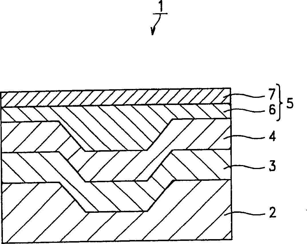
[0022] Such as figure 1 As shown, an optical disc 1 according to the present invention comprises a substrate 2 , a reflective layer 3 , a recording layer 4 and a light-transmitting layer 5 . Layers 3, 4 and 5 are sequentially stacked on the substrate 2. The light beam is applied to the recording layer 4 through the light-transmitting layer 5 , thereby recording and reproducing data signals on and from the recording layer 4 .

[0023] The substrate 2 is made of a resin such as polycarbonate or amorphous polyolefin resin. The substrate 2 has a thickness of 0.3 mm or more.

[0024] Reflective layer 3 is provided on the back of recording layer 4 to reflect light beams applied thereto. Layer 3 is made, for example, of Al or an Al alloy.

[0025] The recording layer 4 is a layer on which data signals are recorded. In this embodiment, the layer 4 is made of a ...


PUM

PropertyMeasurementUnit
wavelengthaaaaaaaaaa
thicknessaaaaaaaaaa
thicknessaaaaaaaaaa

Abstract

An optical disc comprising a substrate and a recording layer and a light-transmitting layer, laid on a substrate one upon the other in the order mentioned. A light beam is applied to the recording layer through the light-transmitting layer, to record and / or reproduce data on the disc. The light-transmitting layer is composed of at least two material layers laid one on the other and having different refractive indices. The disc is designed to set the spherical aberration caused by an objective lens that focuses the light beam used to record and / or reproduce data, at a value close to a minimum.

Description

technical field [0001] The present invention relates to an optical disc having a light-transmitting layer through which a data signal is recorded on the optical disc and from which the recorded data signal is reproduced. Background technique [0002] Optical discs used hitherto each include a recording layer, a reflective layer, etc., which are stacked on each other on a substrate. The light beam is applied to the recording layer of the optical disc, thereby recording data signals on the optical disc. Another light beam is applied to the recording layer, thereby reproducing the data signal recorded on the recording layer. There is a need to increase the recording density of optical discs so that as much data as possible can be recorded on each optical disc. Various techniques have been proposed to meet this demand. [0003] An increase in the recording density of optical discs, that is, the storage capacity per disc, can be achieved in a number of ways. One method is to ...

Claims


Application Information

Patent Timeline
Patent Type & Authority Applications(China)
IPC IPC(8): G11B7/24056G11B7/24067
CPCG11B7/24067G11B7/24056G11B7/252
Inventor 山崎刚山本健二柏木俊行
Owner SONY CORP
Features
  • R&D
  • Intellectual Property
  • Life Sciences
  • Materials
  • Tech Scout
  • Unparalleled Data Quality
  • Higher Quality Content
  • 60% Fewer Hallucinations
Learn More