Ink box

A technology of ink cartridges and ink chambers, used in printing and other directions, can solve the problems of impact damage to the print head, contamination of the printer and printing media, etc., and achieve the effect of avoiding ink leakage

Inactive Publication Date: 2003-12-03
PRINT RITE UNICORN IMAGE PROD CO LTD
View PDF1 Cites 8 Cited by
  • Summary
  • Abstract
  • Description
  • Claims
  • Application Information

AI Technical Summary

Problems solved by technology

When a new ink cartridge is installed, the ink supply needle pierces the seal instantly and enters the ink supply chamber. Since the volume of the ink supply chamber is not much larger than the volume of the ink supply needle it accommodates and the incompressibility of the liquid, the ink in the ink supply chamber At this moment, under a high pressure, the ink will be extruded from the inner hole of the ink supply needle through the print head, polluting the printer and the printing medium. When the pressure is large enough, the ink will impact and damage the print head.

Method used


Image

  • Ink box
  • Ink box
  • Ink box

Examples


no. 1 example

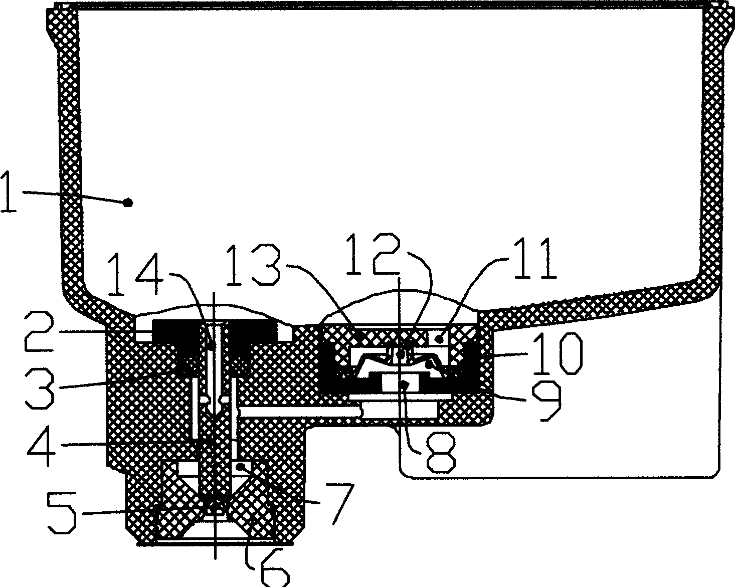
[0028] see figure 1 , figure 2 , there is a seal 6 built into the ink outlet, the stopper 5 is connected with the seal 6 through a thin annular film, and there is a one-way valve between the ink chamber 1 and the ink outlet, and the one-way valve has a through hole The bottom cover 10 of 8, the spool 9 with the central through hole 12 and the gland 13 with the through hole 11 are combined, and the spool 9 made of elastic material relies on its own elasticity to make the valve core with the central through hole The head of 12 is pressed tightly on the valve face of gland 13. The ink supply chamber 7 is the space between the valve surface and the stopper 5 . There is a prosthesis 4 on the axis where the ink supply needle 15 enters, and the prosthesis 4 is in clearance fit with the bush 2 fixed on the box body, and the sealing ring 3 ensures that when the prosthesis 4 moves axially relative to the bush 2, both The tightness between them is to ensure positive and equal volume...

no. 2 example

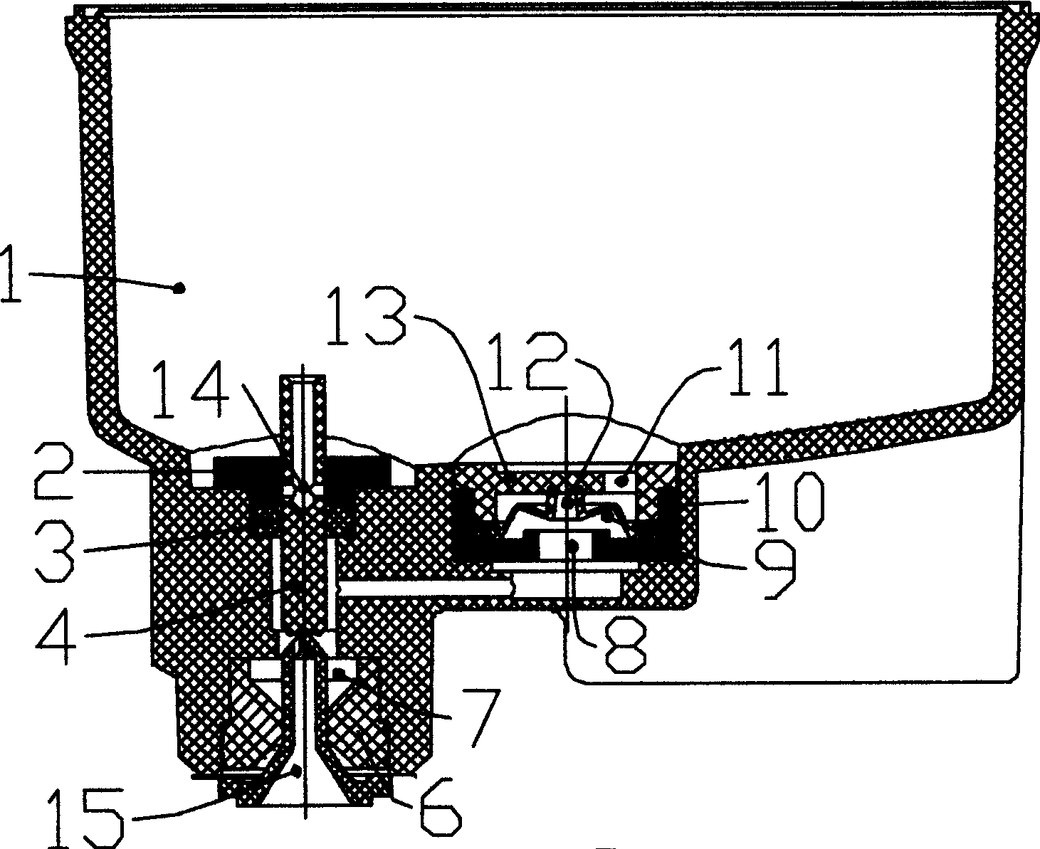
[0030] See Figure 3, Figure 4 , there is a seal 6 built into the ink outlet. Unlike the previous example, this example cancels the stopper. As can be seen from the figure, its function can be completed by the end of the prosthesis 4 located in the seal 6, and the outer end of the ink outlet There is a sealing film 16, and there is a one-way valve between the ink chamber 1 and the ink outlet. The gland 13 is combined, and the valve core 9 made of elastic material has the elasticity that the valve core 9 has by itself, so that the head with the central through hole 12 is pressed tightly on the valve surface of the gland 13. The ink supply chamber 7 is a space between the valve surface and the sealing member 6 . There is a prosthesis 4 on the axis where the ink supply needle 15 enters, and the prosthesis 4 is in clearance fit with the bush 2 fixed on the box body, and the sealing ring 3 ensures that when the prosthesis 4 moves axially relative to the bush 2, both The tightness...

no. 3 example

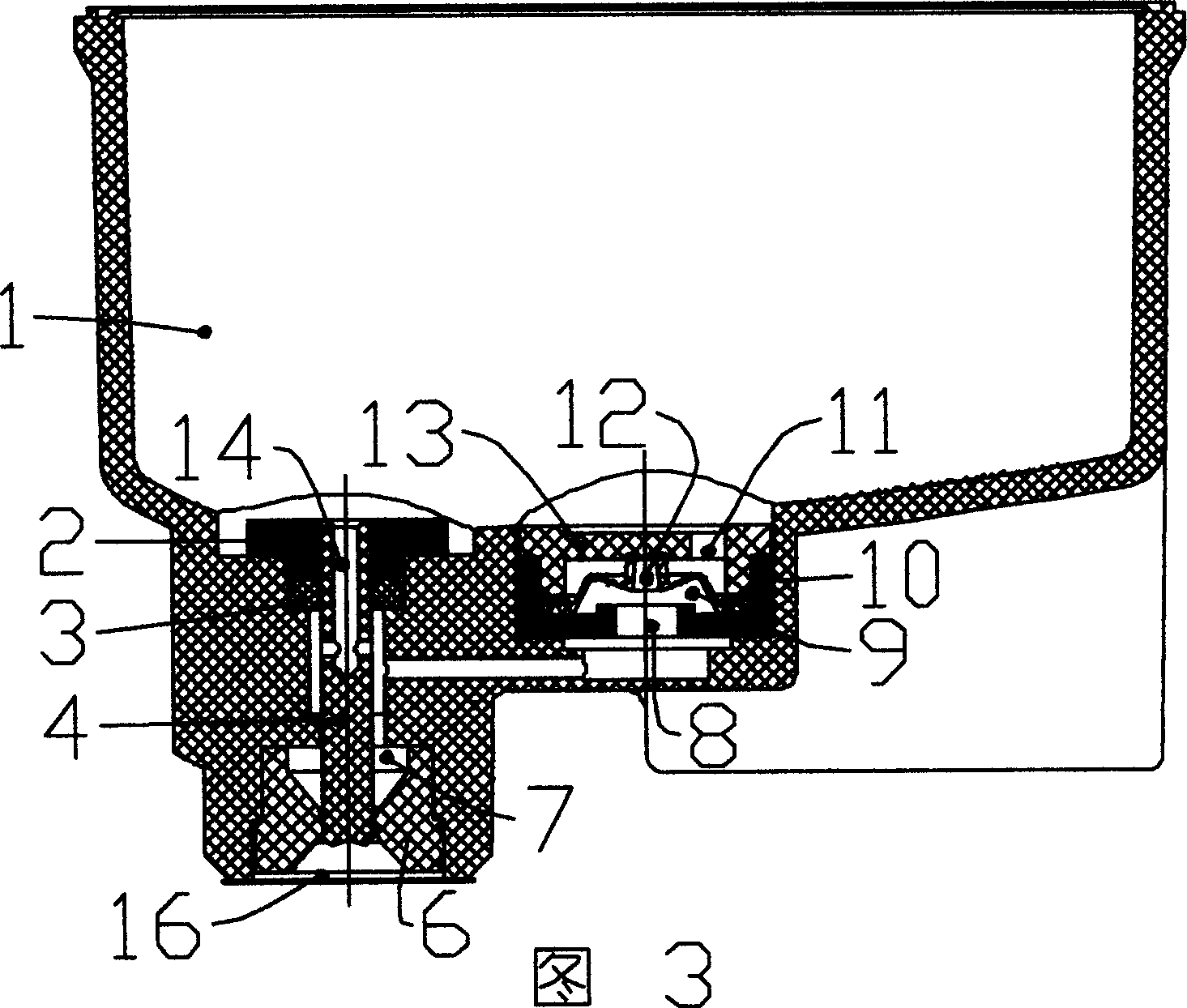
[0032] Referring to Fig. 5, there is a seal 6 built into the ink outlet, the stopper 5 is connected with the seal 6 through a thin annular film, and there is a one-way valve between the ink chamber 1 and the ink outlet, and the one-way valve is controlled by a The bottom cover 10 that has through hole 8, the spool 9 that has center through hole 12 and the gland 13 that has through hole 11 are combined to form, and the spool 9 that elastic material is made relies on the elasticity that self has, makes with The head of the central through hole 12 is tightly pressed against the valve surface of the gland 13 . The ink supply chamber 7 is a space between the valve surface and the sealing member 6 . There is a pressure relief passage between the ink chamber 1 and the ink supply chamber 7, and a one-way pressure relief valve 17 for pressure relief is reversely arranged in the passage, that is, the valve only works when the pressure of the ink supply chamber 7 reaches or exceeds the t...


PUM


Abstract

An ink box for ink-jet printer is composed of an ink cavity full of ink and communicated with atmosphere via air hole on cover, an ink outlet, an one-way valve between the ink cavity and the ink outlet, an ink supplying cavity between the one-way valve and the ink outlet and with an ink supplying needle prothesis in it, and a channel between the ink cavity and the ink supplying cavity and with a pressure releasing unit in it for preventing ink leakage to damage printhead. When an ink supplying needle comes in the ink supplying cavity via the ink outlet, the needle prothesis is withdrawn from the cavity to make the ink volume constant.

Description

technical field [0001] The present invention relates to ink cartridges used in ink jet printers. Background technique [0002] Inkjet printers usually use an ink cartridge that can be separated from the host to supply ink to the print head. The main structure of the ink cartridge is an ink chamber for containing ink, and there is an air hole on the top of the ink chamber that communicates with the ink chamber and the atmosphere. There is an ink outlet in the lower part. When the ink cartridge is loaded into the printer, the ink outlet or the sealing member installed in the ink outlet is sealed and docked with the ink supply needle of the print head. In order to ensure that the ink in the ink chamber can be continuously and stably supplied to the print head, The earlier technical solution is to put a porous substance, such as sponge, in the ink chamber. This type of ink cartridge solves the problem of continuous and stable ink supply well. [0003] The ink cartridges inserte...

Claims


Application Information

Patent Timeline
Patent Type & Authority Applications(China)
IPC IPC(8): B41J2/175
Inventor 萧庆国
Owner PRINT RITE UNICORN IMAGE PROD CO LTD
Why Eureka
Try Eureka