Door cover lock control circuit
A control circuit and door cover lock technology, which is applied to building locks, non-mechanical drive-operated locks, and other washing machines, etc., can solve the problems of damaged door cover locks, failure to operate, and easy damage, and achieve the effect of enhancing security.
- Summary
- Abstract
- Description
- Claims
- Application Information
AI Technical Summary
Problems solved by technology
Method used
Image
Examples
Embodiment 1
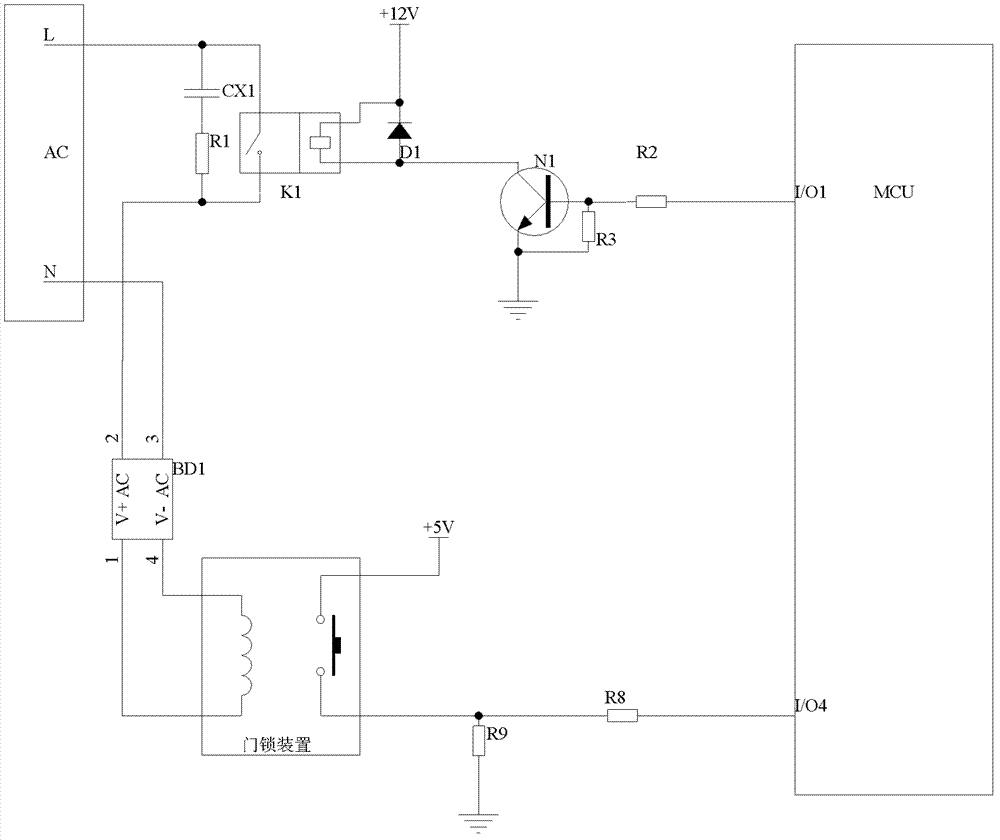
[0025] Such as figure 1 As shown, the door cover lock control circuit of this embodiment includes: a single chip microcomputer (MCU), a door cover state detection circuit, and a strong current control circuit. The door cover state detection circuit is connected with the door cover lock and the single-chip microcomputer for detecting the state of the door cover. The strong current control circuit is connected with the strong current, the door cover lock and the single-chip microcomputer. Access to the door lock to control the opening or closing of the door.
[0026] Specifically, the heavy current control circuit includes: a relay sub-circuit and a triode control sub-circuit. The relay sub-circuit includes: relay K1, diode D1, resistor R1 and capacitor CX1, the triode control sub-circuit includes: triode N1, resistor R2 and resistor R3, resistor R3 is connected between the base and emitter of triode N1, and the resistor R2 is connected between the base of the transistor N1 an...
Embodiment 2
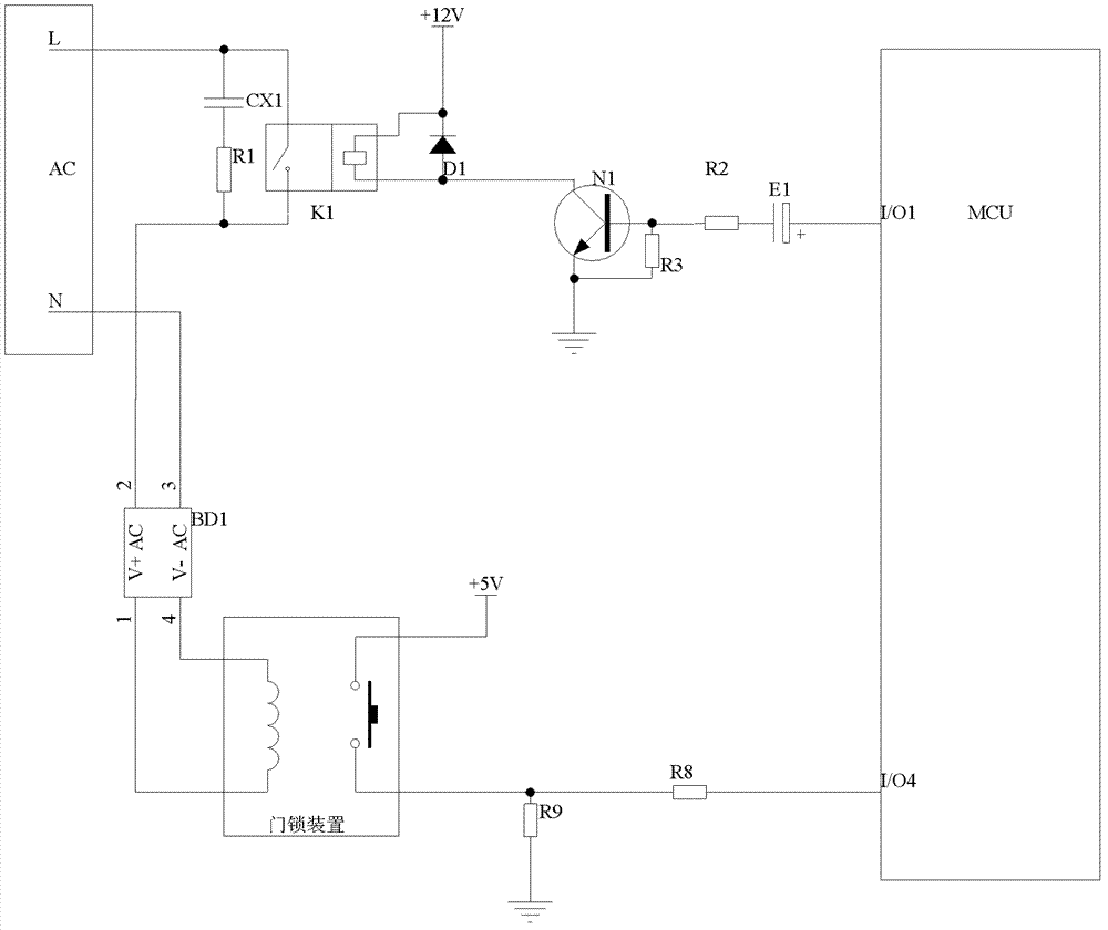
[0032] The structure of the door cover lock control circuit in this embodiment is basically the same as the circuit structure in Embodiment 1, the difference is that an electrolytic capacitor is connected in series between the strong current control circuit and the microcontroller, that is, the resistor R2 and the output port I / O1 of the MCU The electrolytic capacitor E1 is connected in series. Because the inner coil of the door cover lock is energized for 100 milliseconds, the door cover lock can perform locking and unlocking actions. If the time is too long, the coil will heat up, and if the time is too long, the door lock will be damaged. Therefore, an electrolytic capacitor E1 is connected in series at the outlet of the output port I / O1 of the MCU. When the door lock needs to be opened or closed, the I / O1 port of the MCU needs to output a high level (I / O1=1), and under normal circumstances The time of high level is 100ms (TH=100ms). When the time of high level of I / O1 port...
Embodiment 3
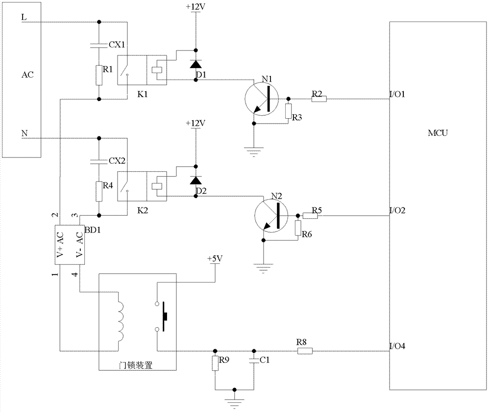
[0035] The door cover lock control circuit structure of this embodiment is basically the same as that of Embodiment 1, the difference is that two roads of strong current control circuits are used in this embodiment, and the structure of each road of strong current control circuit is the same as that of Embodiment 1. The structure of the heavy current control circuit is the same. One end of the relay K1 contact of the first heavy current control circuit is connected to the live wire terminal L, the other end is connected to the input terminal 2 of the rectifier BD1, and R2 in the triode control sub-circuit is connected to the output port I / O1 of the MCU. One end of the relay K1 contact of the second strong current control circuit is connected to the fire wire terminal N, the other end is connected to the input terminal 3 of the rectifier BD1, and R5 in the triode control sub-circuit is connected to the output port I / O2 of the MCU. Due to the addition of a strong current control...
PUM
 Abstract
Description
Claims
Application Information
 - R&D
- Intellectual Property
- Life Sciences
- Materials
- Tech Scout
- Unparalleled Data Quality
- Higher Quality Content
- 60% Fewer Hallucinations
Browse by: Latest US Patents, China's latest patents, Technical Efficacy Thesaurus, Application Domain, Technology Topic, Popular Technical Reports.
© 2025 PatSnap. All rights reserved.Legal|Privacy policy|Modern Slavery Act Transparency Statement|Sitemap|About US| Contact US: help@patsnap.com


