Synchronous air brake system controlled by electric current

A technology of current control and synchronous coordination, applied in the direction of brakes, brake components, transportation and packaging, etc., can solve the problems of asynchronous braking of front and rear wheels, and achieve the effect of synchronous braking of front and rear wheels and fast transmission speed

Inactive Publication Date: 2005-11-23
BEIJING TINGYI BRAKING CO LTD
View PDF0 Cites 4 Cited by
  • Summary
  • Abstract
  • Description
  • Claims
  • Application Information

AI Technical Summary

Problems solved by technology

[0003] The purpose of the present invention is to solve the technical problem that the front and rear wheels of long-wheelbase vehicles are not synchronously braked in the prior art, and to provide a current-controlled air pressure braking system that enables synchronous and coordinated braking of the front and rear wheels of the vehicle, thereby improving the braking performance of the vehicle in an all-round way , greatly eliminating potential safety hazards caused by asynchronous braking

Method used


Image

  • Synchronous air brake system controlled by electric current

Examples


Embodiment Construction

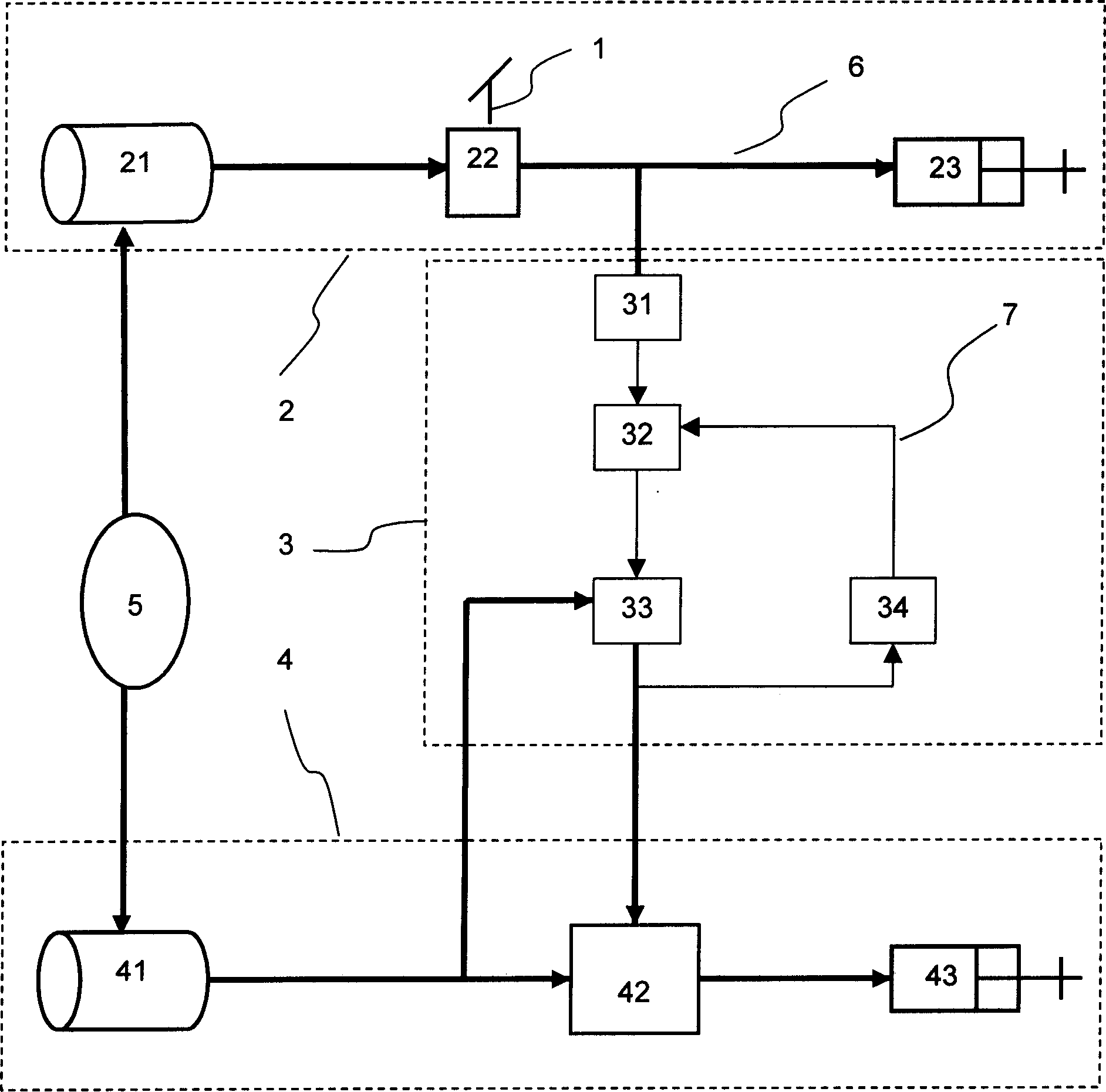
[0025] The technical solution of the present invention will be described in detail below with reference to the drawings.

[0026] figure 1 It is a schematic diagram of the structure of the present invention. Such as figure 1 As shown, the current control synchronous and coordinated pneumatic braking system of the present invention is composed of a front braking unit 2, a current control unit 3, and a rear braking unit 4 connected in sequence. The front brake unit 2 includes a front air tank 21, a brake valve 22, and a front brake air chamber 23 connected in sequence. When the driver of the automobile steps on the brake valve 22, the compressed air in the front air storage tank 21 connected with the air compressor 5 enters the brake air chamber 23 through the brake valve 22, and the front brake push rod acts to push the adjusting arm to brake. The rear brake unit 4 includes a rear air tank 41, a relay valve 42 and a rear brake air chamber 43 connected in sequence. The relay valve ...


PUM


Abstract

This invention relates to an electric control synchronous coordinate air-pressure brake system, which provides a new air-pressure brake technology project controlled by electric signal. When the front wheel brakes, the front gas reservoir compresses air and enters the front brake air cushion through the brake valve, the first electric pressure transformer turns the pressure that output by the brake valve into the electric signal, and the single flake intelligent control deals with the back pressure electric valve to output the pressure signal that controls the open of the relay valve, the compressed air in back gas reservoir enters the back braking air chamber to achieve the back wheel braking. The output end of the pressure electric valve has the second electric pressure transformer, which turns the output pressure into the electric signal, and sends the signal back to the control to form the closed-loop control circuit, which makes the front braking air chamber consistent to the back braking air chamber. Because the telecommunication transmission seldom delays, so this invention achieves the real synchronous coordinate braking.

Description

Technical field [0001] The present invention relates to pneumatic braking, in particular to a long-distance pneumatic braking system that is synchronized and controlled by micro-current. Background technique [0002] Large and medium-sized cars, trains, urban light rail cars, etc. generally use pneumatic braking, but when braking, such as semi-trailers and full trailers, tractors and trailers often collide, bounce, slip, tail, fold, and even roll. , Causing traffic accidents. The main reason is that the front and rear brakes are not synchronized and coordinated. The current pneumatic brake is when the driver steps on the brake plate to open the brake valve. The brake valve outputs gas with different pressures in proportion to the pedaling force. The gas reaches the front and rear wheels through the air pipe. The gas directly enters the front wheel air chamber to push the connecting rod to implement the front wheel brake. The air reaches the relay valve located on the rear wheel t...

Claims


Application Information

Patent Timeline
Patent Type & Authority Applications(China)
IPC IPC(8): B60T17/00
Inventor 王庭义张玉林
Owner BEIJING TINGYI BRAKING CO LTD
Why Eureka
Try Eureka