Injection molder

A technology for injection molding and forming machines, which is applied in the field of injection molding machines, and can solve problems such as deflection of fixed templates, lack of connecting rods, skewing, etc.

Inactive Publication Date: 2003-12-10
FANUC LTD
View PDF2 Cites 4 Cited by
  • Summary
  • Abstract
  • Description
  • Claims
  • Application Information

AI Technical Summary

Problems solved by technology

In addition, since the lower connecting rod is fixed on the machine base itself, it hardly prevents the fixed plate from being skewed due to the contact force of the nozzle.
However, on the other side's diagonal, no connecting rods are set
Therefore, although the lower part of the fixed template is fixed on the machine base, the connecting rod is not fixed at the upper position on the diagonal, and is in a free state.
As a result, when the nozzle contact force is applied to the fixed plate, there will be abnormal phenomena such as deflection and skew of the fixed plate at the corner where the connecting rod is not connected.

Method used


Image

  • Injection molder
  • Injection molder
  • Injection molder

Examples


Embodiment Construction

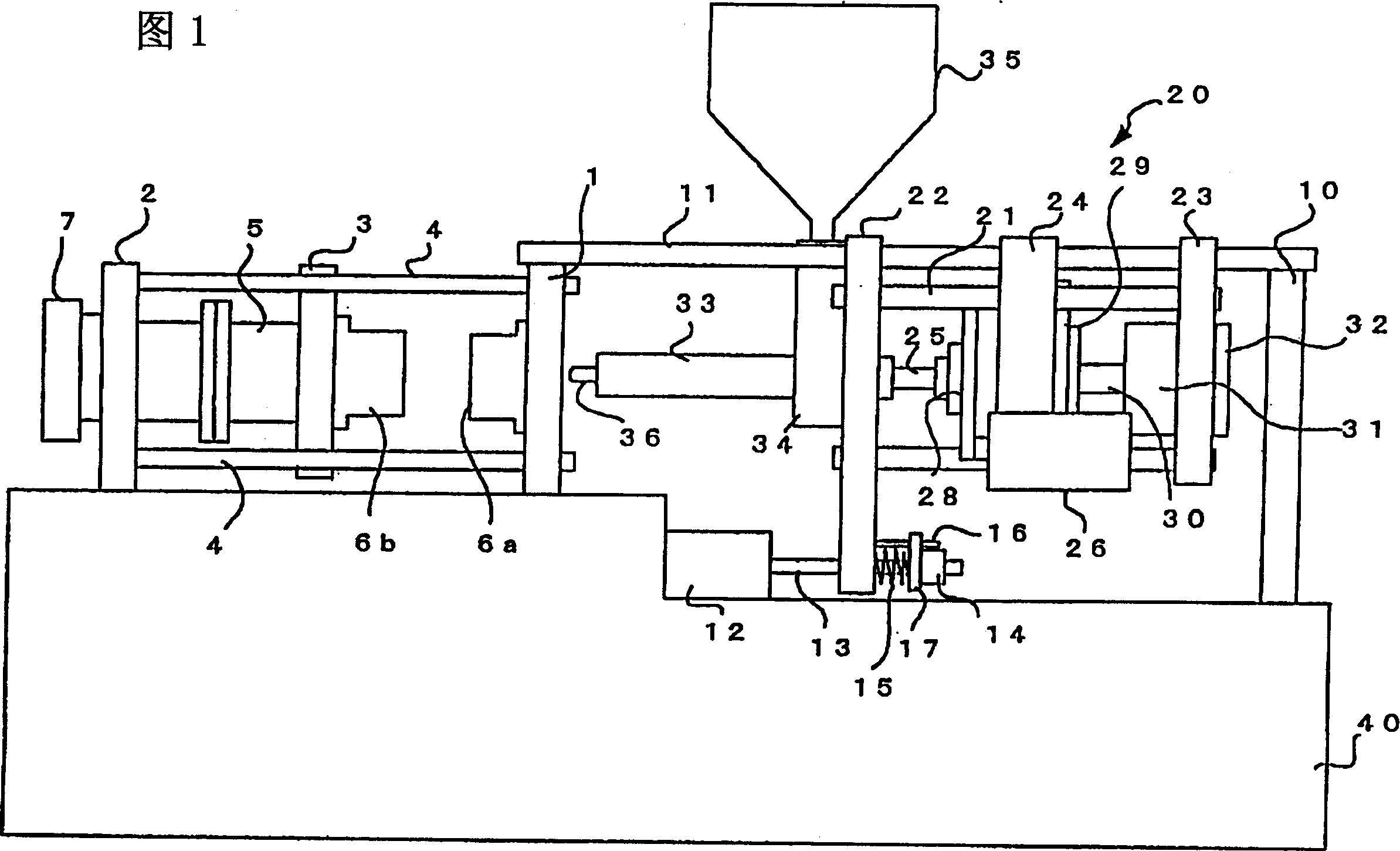
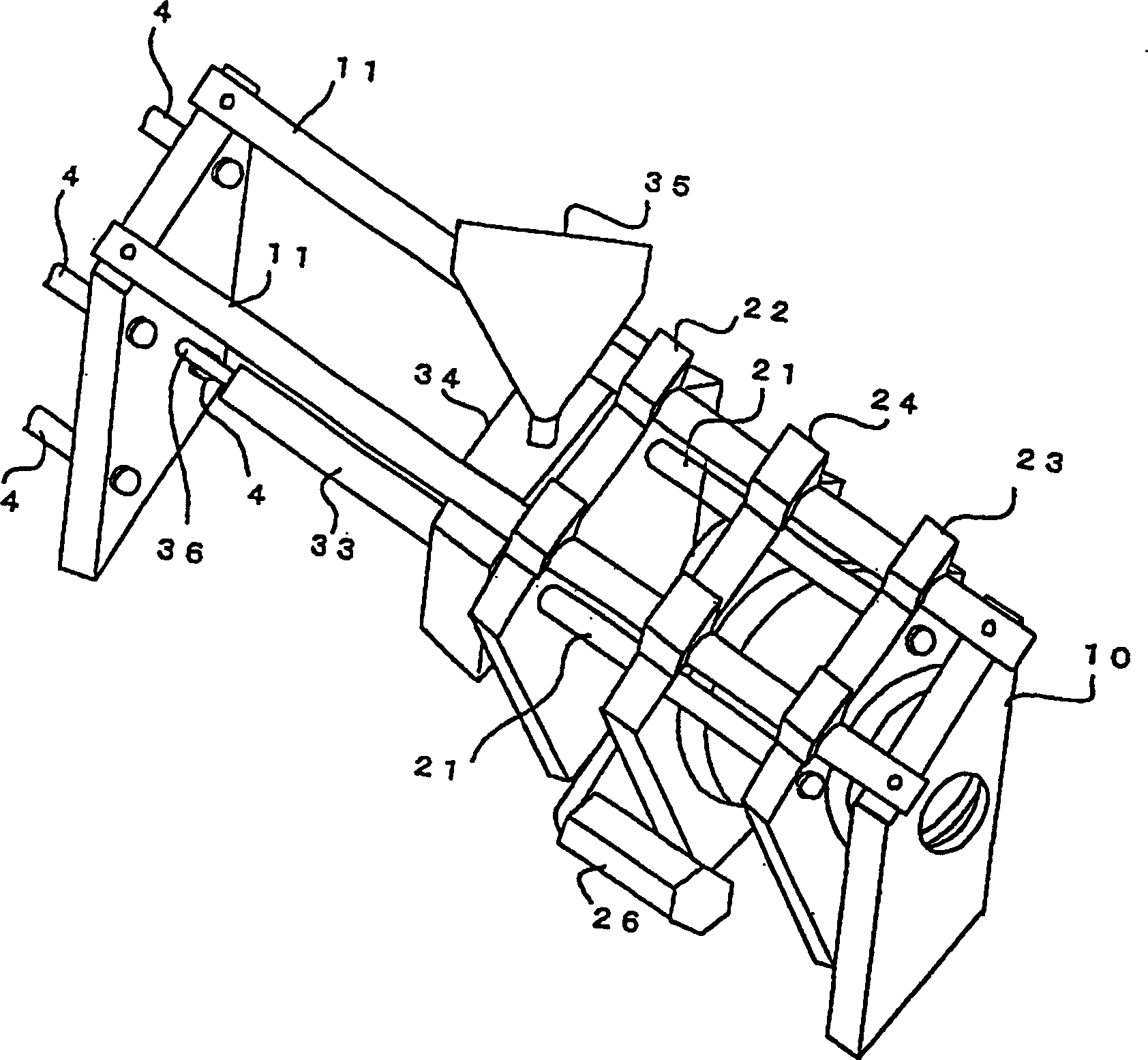
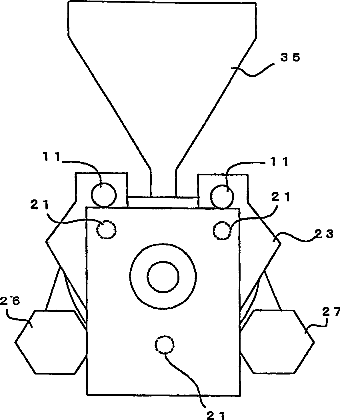
[0020] Fig. 1 is a front view of an injection molding machine according to an embodiment of the present invention. figure 2 It is a perspective view of the injection device side. image 3 It is a side view seen from the right side of Figure 1. A fixed template 1 is fixed to the machine base 40, and a mold clamping mechanism is arranged on one side of the fixed template 1. That is, the back platen 2 forming a part of the mold clamping mechanism is installed above the machine base 40, and four connecting rods 4 are installed between the back platen 2 and the fixed template 1. Between the back platen 2 and the fixed template 1, the movable template 3 is slidably mounted on the four connecting rods 4, and guided by the connecting rods 4, it can move in the left-right direction in FIG. 1. A clamping mechanism 5 is arranged between the back platen 2 and the movable template 3. On the fixed template 1, a fixed side metal mold 6 a is installed, and a movable side metal mold 6 b is instal...


PUM


Abstract

The present invention relates to an injection molding machine, and more specifically, to an injection molding machine having a mold clamping mechanism and an injection unit arranged horizontally on a base. A block member is fixed to the base of a horizontal injection molding machine. The block member and a stationary platen fixed to the base are connected by means of connecting members. In nozzle touch operation, an injection nozzle of the injection unit presses against the stationary platen. Although this pressing force of the injection nozzle urges the stationary platen to fall down, the connecting members and the block member prevent the stationary platen from falling down.

Description

Technical field [0001] The invention relates to an injection molding machine, in particular to an injection molding machine in which a clamping mechanism and an injection mechanism are arranged transversely to a machine base. Background technique [0002] In the horizontal injection molding machine, a fixed template is set upright on the base, and a fixed metal mold is installed on one side of the fixed template. The movable metal mold is moved through the mold clamping mechanism, and the metal mold is opened and closed. At the same time, close the mold. On the other hand, on the other side of the fixed template, an injection device is arranged. When the nozzle contacts, the injection nozzle of the injection device is pushed onto the runner sleeve of the fixed side metal mold fixed on the fixed template. During injection, the injection device is driven to inject the molten resin into the cavity of the metal mold in a state where the injection nozzle is pressed against the sprue b...

Claims


Application Information

Patent Timeline
Patent Type & Authority Applications(China)
IPC IPC(8): B29C45/20B29C45/17
CPCB29C45/1761B29C2045/1792B29C45/1777B29C45/1744
Inventor 吉冈光志
Owner FANUC LTD
Why Eureka
Try Eureka