Plasma display device and method for setting driving operation

A plasma and display device technology, applied to static indicators, color TV parts, TV system parts, etc., can solve problems such as reduced luminous efficiency, and achieve the effect of reducing design work

Inactive Publication Date: 2003-12-17
HITACHI CONSUMER ELECTRONICS CORP
View PDF0 Cites 1 Cited by
  • Summary
  • Abstract
  • Description
  • Claims
  • Application Information

AI Technical Summary

Problems solved by technology

as Figure 16 As shown in , there is a problem in the conventional method that when the luminance is increased, the luminous efficiency decreases

Method used


Image

  • Plasma display device and method for setting driving operation
  • Plasma display device and method for setting driving operation
  • Plasma display device and method for setting driving operation

Examples


Embodiment Construction

[0035] The present invention will be described more specifically below with reference to examples and drawings.

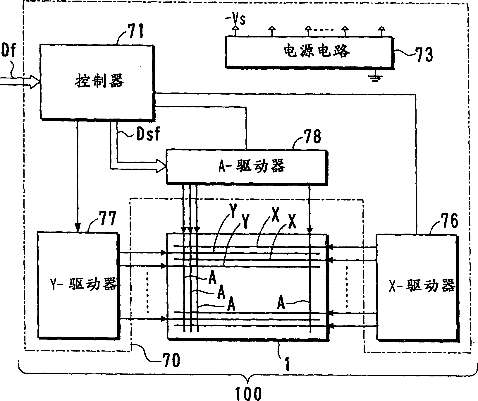
[0036] figure 1 is a block diagram showing a plasma display device according to the present invention. The plasma display device 100 includes a PDP 1 having a three-electrode structure, a 32-inch color display screen, and a driving unit 70 for controlling the unit to emit light. The plasma display device 100 is used as a wall-mounted television, a monitor of a computer system, and the like.

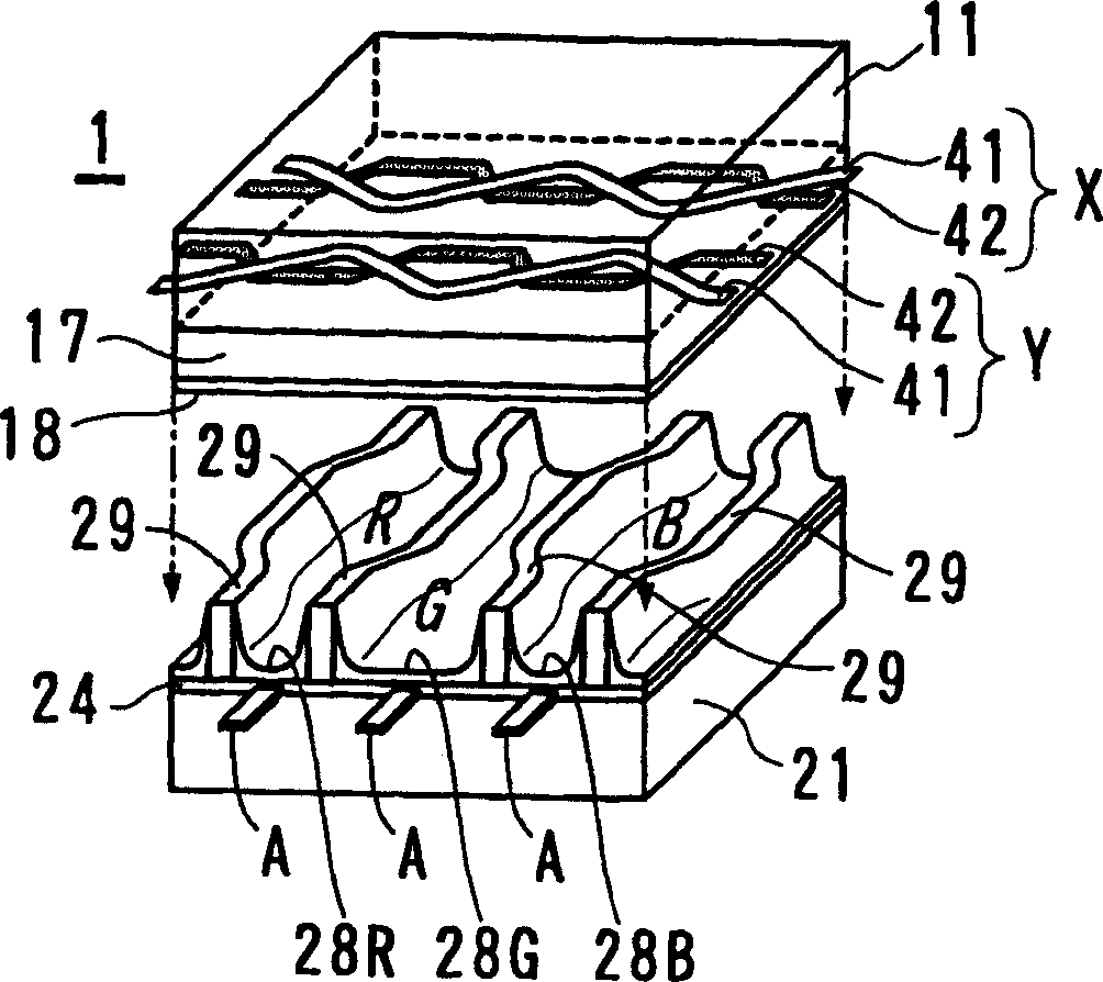
[0037] The PDP 1 includes a pair of base structures representing a structural body including electrodes and other constituent parts provided on a glass substrate. In the PDP 1, display electrodes X and Y constituting an electrode pair for generating a display discharge are arranged in the same direction, and an address electrode A is arranged so as to pass through the display electrodes X and Y. The display electrodes X and Y extend along the row direction of the screen (i...


PUM


Abstract

A plasma display device having improved luminance and light emission efficiency in display discharge without a shortening of its life is provided. The plasma display panel(1) has a structure including a discharge gas space and fluorescent materials (28R,G,B) between the display electrodes (X,Y) and the address electrodes (A). After the addressing process for forming wall charge in cells to be lit, a drive operation is performed for changing a potential of at least one display electrode (X) so as to be different between the start time point and the end time point of the display discharge for generating display discharge and the following reformation of the wall charge in the cell, and the cell voltage between the display electrode(X) and the address electrode(A) at the start time point of the display discharge is set to a value lower than a microdischarge start voltage that is measured in advance.

Description

technical field [0001] The present invention relates to a plasma display device displaying images using a plasma display panel (PDP) and a method of setting an operation of a driving circuit for driving the plasma display panel. [0002] Plasma display devices are becoming commonplace just as televisions have large screens. In order to make it more popular, it is necessary to improve the performance of the plasma display device. Since the luminous efficiency of the current plasma display device is not as good as that of the liquid crystal display device, it is particularly urgent to improve the luminous efficiency determined by the ratio of luminance to power loss. Background technique [0003] As a color display device, a surface discharge AC type PDP is known. The surface discharge type has a three-electrode structure in which first and second display electrodes, which are anodes and cathodes in display discharge for determining the light emission amount of a cell, are p...

Claims


Application Information

Patent Timeline
Patent Type & Authority Applications(China)
IPC IPC(8): H04N5/66G09G3/20G09G3/288G09G3/291G09G3/294G09G3/296G09G3/298
CPCG09G3/2942G09G3/2983G09G3/296
Inventor 糸川直樹瀨尾欣穗橋本康宜
Owner HITACHI CONSUMER ELECTRONICS CORP
Why Eureka
Try Eureka