Control valve

A technology for controlling valves and spools, applied in control valves, valve details, valve devices, etc., to solve problems such as lack of stability in closing performance

Inactive Publication Date: 2003-12-17
BERMAD PARTNERSHIP
View PDF1 Cites 6 Cited by
  • Summary
  • Abstract
  • Description
  • Claims
  • Application Information

AI Technical Summary

Problems solved by technology

[0004] A hitherto unresolved problem with this type of control valve is the lack of stability in closing performance

Method used


Image

  • Control valve
  • Control valve
  • Control valve

Examples


Embodiment Construction

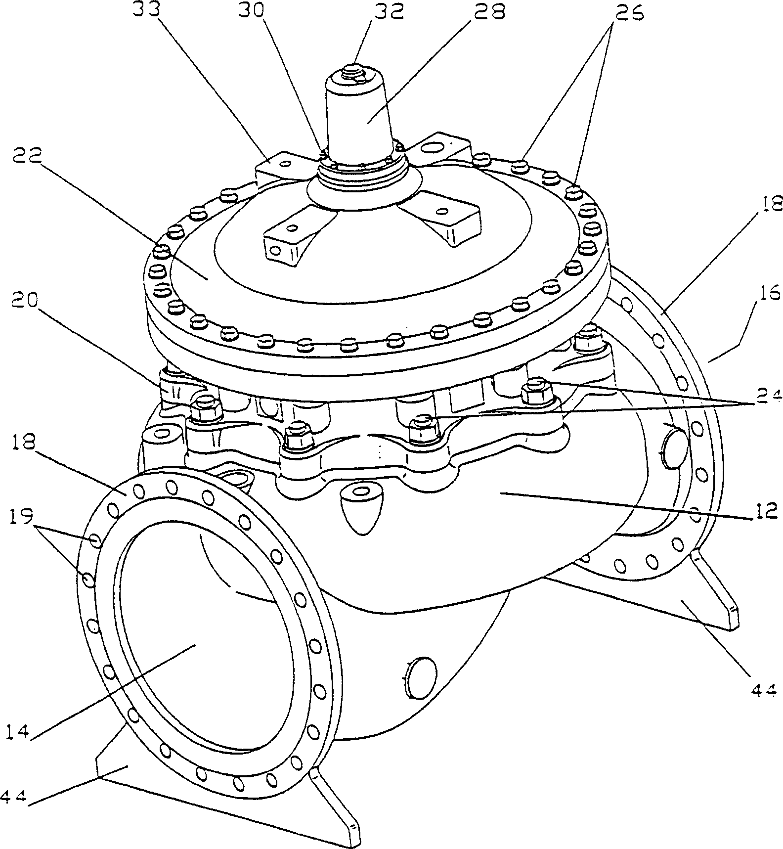
[0043] The unique control valve of the present invention is designed to control the flow of fluid, which may be liquid or gas. The control valve of the present invention is preferably controlled hydraulically, but may also be operated electrically or otherwise. The control valve of the present invention can be equipped with a check valve, which can be automatically controlled when the flow pattern changes.

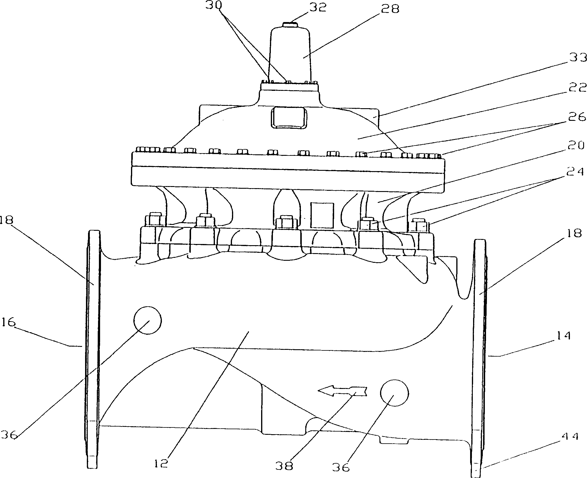
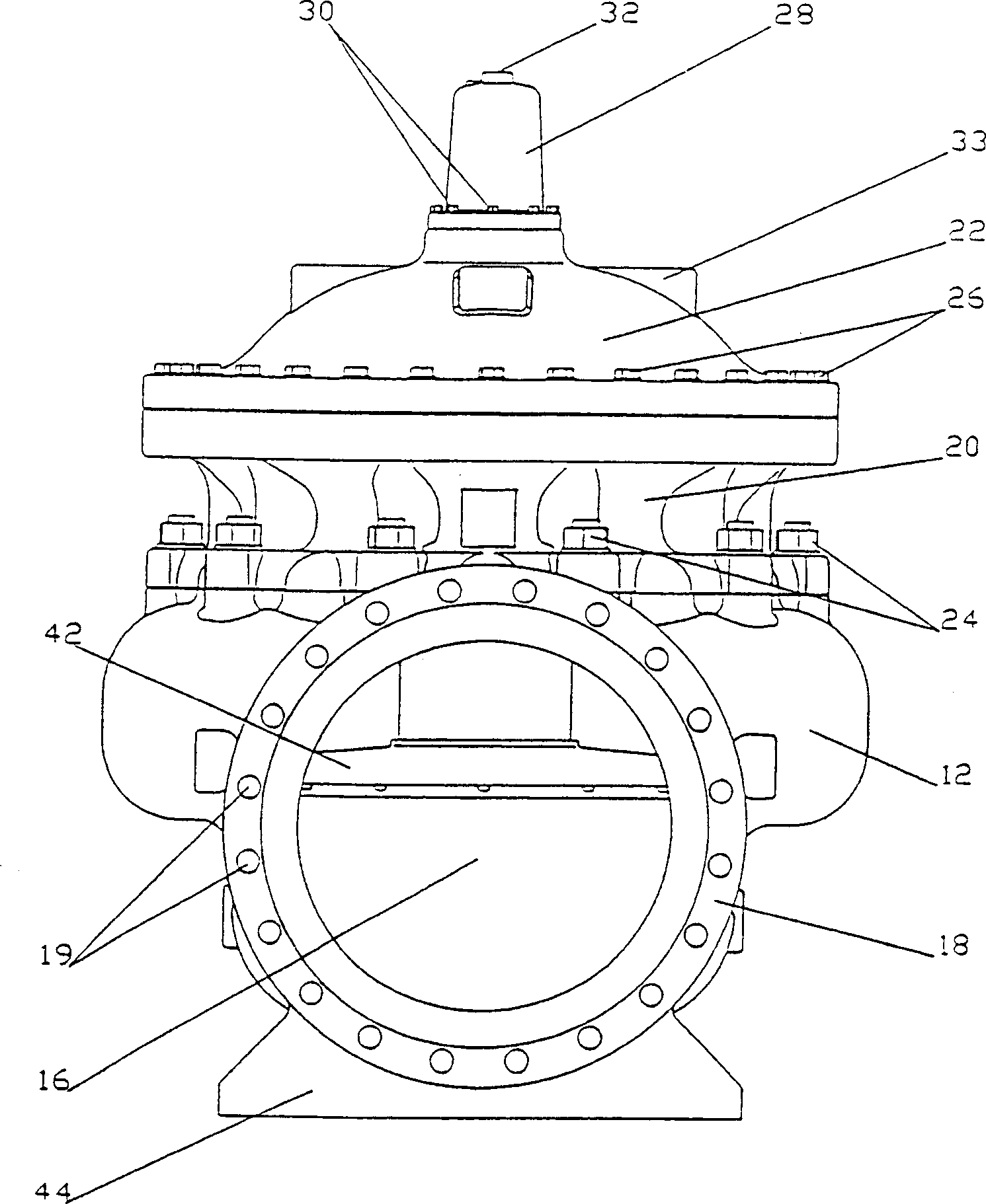
[0044] see figure 1 , which shows an isometric view of a control valve according to a preferred embodiment of the present invention. The control valve 10 has a wide body 12 which is substantially spherical in shape. The body 12 is equipped with an inlet 14 (upstream) and an outlet (downstream) 16, both having flanges 18 for connecting the control valve 10 to a pipeline (not shown in the figure). In order to connect the control valve 10 to the pipeline, the flange 18 has holes 19 through which bolts can be screwed onto corresponding flanges on the edge of the pipeline. ...


PUM


Abstract

A control valve for regulating flow of fluids passing through the valve. The control valve includes a body with an inlet, an outlet and a passageway through which the fluid passes from the inlet to the outlet. The control valve also includes a displaceable column provided with an internal and concentric bolt, the displaceable column is actuated by an actuator, the actuator positioned in a chamber that is connected to the body, a valve closure attached to the displaceable column. The displaceable column moves between a most retracted position, in which the inlet is fluidically communicating with the outlet, and a most pulled out position, in which the valve closure sealingly blocks the passage of fluid through the control valve.

Description

technical field [0001] The present invention relates to a fluid control valve, and more particularly, the present invention relates to a stable control valve having a dual chamber driver. Background technique [0002] Fluid control valves are well known in the prior art. Control valves are used to regulate or completely shut off the flow of liquid streams (organic or inorganic) and gaseous systems. [0003] The inventor Weingarten introduced a diaphragm type control valve in US Patent No. 5,383,646 filed in 1994 and entitled "Diaphragm Control Valve". The diaphragm type control valve includes a diaphragm valve element having an outer peripheral portion for securing the diaphragm within the valve chamber, and the control valve includes a valve closing portion movable relative to the valve seat to control flow. The control valve also includes an intermediate elastic portion allowing the valve closing portion to move, and a conical guide portion provided between the valve clo...

Claims


Application Information

Patent Timeline
Patent Type & Authority Applications(China)
IPC IPC(8): F16K31/145A61M39/00F16K15/18F16K31/126F16K31/26F16K37/00
CPCF16K31/1266Y10T137/7853Y10T137/8175Y10T137/8275
Inventor 兹维·温加滕
Owner BERMAD PARTNERSHIP
Why Eureka
Try Eureka