Built-in hydraulic distributor

A hydraulic distributor and distributor technology, applied in the direction of fluid pressure actuators, servo meter circuits, servo motor components, etc., can solve the problems of large empty stroke of the handle, which is not conducive to precise control, etc., and achieve sensitive control and good sealing , the effect of easy maintenance

Active Publication Date: 2016-10-12
SHANDONG HONGYU AGRI MACHINERY
View PDF10 Cites 4 Cited by
  • Summary
  • Abstract
  • Description
  • Claims
  • Application Information

AI Technical Summary

Problems solved by technology

like figure 1 Shown is a traditional hydraulic distributor, which includes a distributor housing and a main control valve, a check valve, and an oil return valve arranged in the distributor housing. The main control valve passes through the main control valve sleeve 13 is installed in the hole of the main control valve, which has the following disadvantages: 1. The static settlement value of the hydraulic lifter is mainly guaranteed by the gap between the main control valve and the main control valve sleeve. The distance that falls by itself within half an hour accounts for the proportion of the entire stroke. The static settlement value of the existing tractor lifter is generally about 4% when it leaves the factory. If it is used for a long time, the static settlement value will drop significantly.
2. When the handle of the hydraulic lifter controls lifting and lowering, the empty stroke of the handle is large, and the lifting segment is between 20 and 40, and the descending segment is between 160 and 180, which is not conducive to precise control

Method used


Image

  • Built-in hydraulic distributor
  • Built-in hydraulic distributor
  • Built-in hydraulic distributor

Examples


Embodiment Construction

[0026] The principles and features of the present invention are described below in conjunction with examples, which are only used to explain the present invention and are not intended to limit the scope of the present invention.

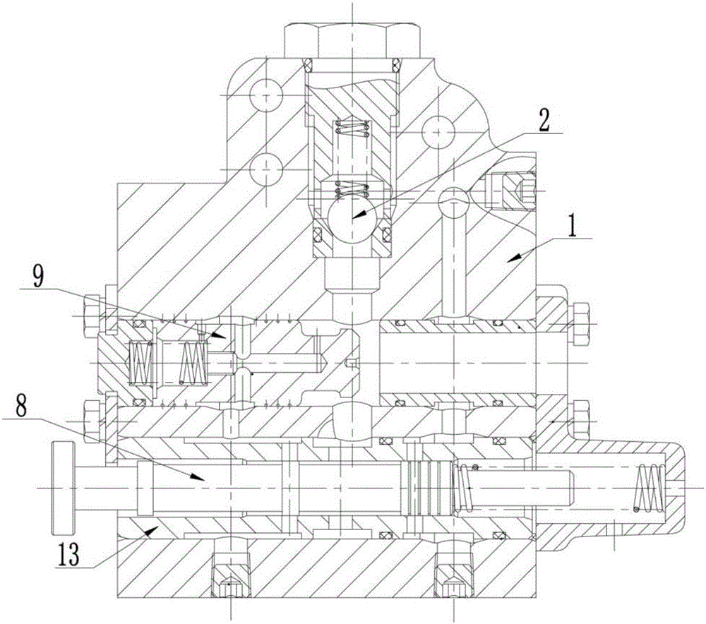
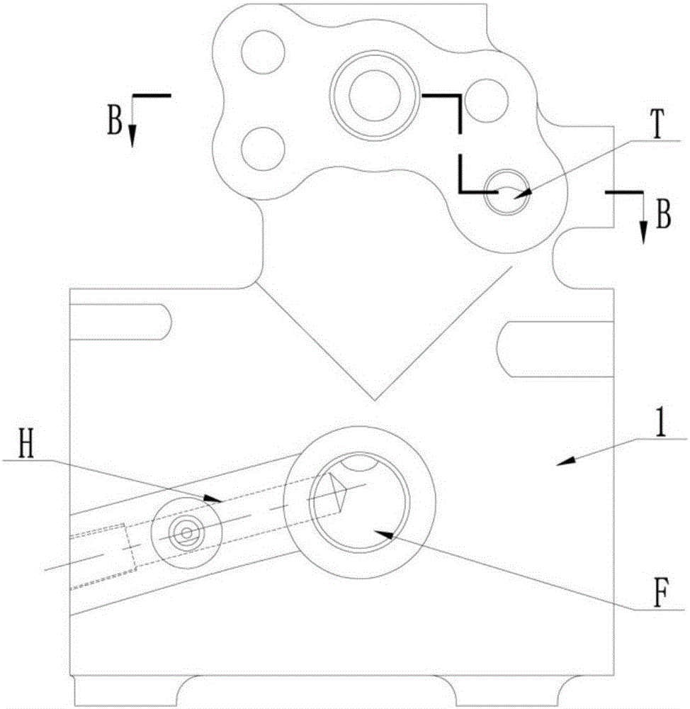
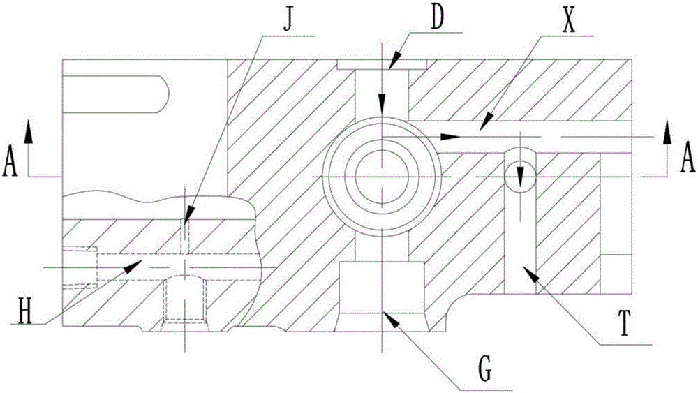
[0027] Such as Figure 2-11 As shown, a built-in hydraulic distributor includes a distributor housing 1, the right side of the distributor housing 1 is provided with a main valve front cover 4, and the inside of the distributor housing is provided with a main control valve 8, a return Oil valve 9, one-way valve 2; the distributor shell is provided with an oil inlet F, an oil cylinder oil inlet D, and an oil return port E; the main control valve is installed in the main control valve hole 12, and the The oil return valve is installed in the oil return valve hole 11, the one-way valve is installed in the one-way valve hole 10, the main control valve hole and the oil return valve hole are connected through the oil return valve control oil circuit H , t...


PUM


Abstract

The invention discloses a built-in hydraulic distributor which comprises a distributor shell and a main control valve, an oil return valve and a check valve which are arranged in the shell; an oil inlet, an oil cylinder oil inlet and an oil return opening are formed in the distributor shell; a lowering valve is arranged in a main control valve hole; a lowering valve compressing sleeve and a lowering valve adjusting bolt are arranged at the right side of the lowering valve; the lowering valve is arranged at the right side of the main control valve; the oil cylinder oil inlet communicates with the oil inlet chamber of the lowering valve by an oil cylinder oil drainage oil line; the oil outlet chamber of the lowering valve communicates with the oil return opening; the lowering valve comprises a lowering valve core and a lowering valve seat; the lowering valve compressing sleeve compresses the lowering valve seat; and the lowering valve adjusting bolt compresses on the lowering valve compressing sleeve. The built-in hydraulic distributor can improve the lowering and lifting sensitivity, and the hydrostatic sedimentation value of a hydraulic lifter is ensured by the sealing state of the lowering valve and the check valve, thus being more reliable, good in airtightness, steady in use performances, high in reliability, and convenient to dismantling and maintenance.

Description

technical field [0001] The invention relates to a hydraulic distributor, in particular to a built-in hydraulic distributor. Background technique [0002] The function of the tractor hydraulic lifter is to connect and pull the farm tools, control the lifting of the farm tools, control the plowing depth of the farm tools, increase the weight of the tractor driving wheels to improve the adhesion performance of the tractor, and output the hydraulic energy to the working machinery for other operations. Among them, the hydraulic distributor is the core component of the hydraulic control system. Its function is to control the pressure, flow and direction of the hydraulic system. It is responsible for controlling the hydraulic lifter to complete actions such as lifting, neutralizing, and descending by controlling the hydraulic cylinder. Its performance has a great impact on the entire tractor hydraulic pressure. Suspension performance has a direct and significant impact. [0003] I...

Claims


Application Information

Patent Timeline
Patent Type & Authority Applications(China)
IPC IPC(8): F15B13/02
CPCF15B13/023F15B2211/405
Inventor 李松燕王兆华尹翔刘建波刘德敏王松浩
Owner SHANDONG HONGYU AGRI MACHINERY
Why Eureka
Try Eureka