3D printing forming method based on skeleton line contour recognition and area segmentation

A 3D printing and area segmentation technology, applied in 3D printing related fields to achieve the effect of high forming accuracy

Active Publication Date: 2021-10-08
HUAZHONG UNIV OF SCI & TECH
View PDF5 Cites 3 Cited by
  • Summary
  • Abstract
  • Description
  • Claims
  • Application Information

AI Technical Summary

Problems solved by technology

[0004] In view of the above defects or improvement needs of the prior art, the present invention provides a 3D printing forming method based on skeleton line contour recognition and regi

Method used


Image

  • 3D printing forming method based on skeleton line contour recognition and area segmentation
  • 3D printing forming method based on skeleton line contour recognition and area segmentation
  • 3D printing forming method based on skeleton line contour recognition and area segmentation

Examples


example

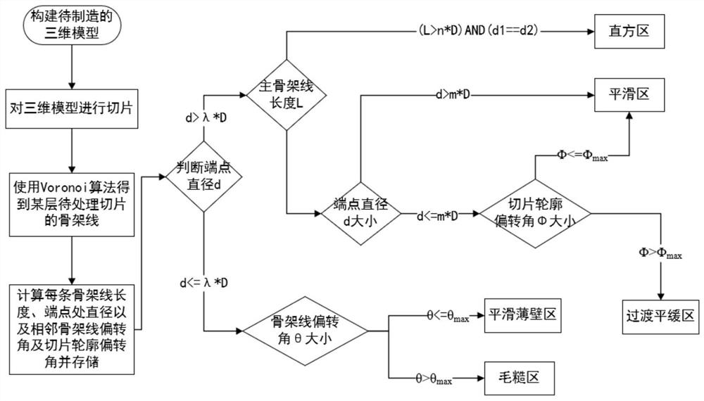
[0051] For this example, the calculation method is: (1) the length of the skeleton line is the distance between the two endpoints; (2) the diameter at the endpoint is the minimum distance between the endpoint and the slice contour. For the center circle, the diameter of the circle is incremented. When the outline segment appears in the circle for the first time, the straight-line distance between the calculated line segment and the end point is the diameter d of the end point; (3) The deflection angle between the two skeleton lines The calculation method is: find two skeleton lines L1 and L2 with the same end point, the end point is P, the other end point of L1 is P1, and the other end point of L2 is P2, then the supplementary angle of ∠P1PP2 on the extension line of P1P That is the deflection angle; (4) The deflection angle between two adjacent sides of a certain point on the original contour is the same as the calculation method of (3) above.

[0052] (e) Identify each regio...


PUM


Abstract

The invention belongs to the technical field related to 3D printing, and discloses a 3D printing forming method based on skeleton line contour recognition and area segmentation. The method comprises the following steps: S1, calculating a skeleton line in each slice layer forming contour; S2, calculating and solving the length of the main skeleton line, the diameter of the end point of each skeleton line, the deflection angle between every two adjacent skeleton lines and the deflection angle between every two adjacent edges in each forming contour; S3, dividing the area types in each forming contour into a straight square area, a smooth area, a transition smooth area, a smooth thin-wall area and a rough area, establishing an area division standard by multiple parameter values obtained through calculation in the step S2, and dividing the areas in each forming contour; and S4, planning a forming path of each area for 3D printing forming. According to the method, the problems of contour recognition and segmentation of complex contour parts are solved, and a complex path planning method with high efficiency and high robustness is provided.

Description

technical field [0001] The invention belongs to the technical field related to 3D printing, and more specifically relates to a 3D printing forming method based on skeleton line contour recognition and region segmentation. Background technique [0002] 3D printing is a common name for additive manufacturing technology. It is completely opposite to the traditional material "removal" processing method, and is an additive manufacturing method. A manufacturing method for printing a three-dimensional solid model to be processed is usually adopted in a layer-by-layer manufacturing manner. One of its key technologies is the path planning technology. For the same model, different path plans have completely different printing effects. Traditional paths such as raster path, zigzag path, profile offset path, helical path, axis conversion path, etc. have good results for specific models, but there are many problems when printing complex models: raster path and zigzag path in There are ...

Claims


Application Information

Patent Timeline
IPC IPC(8): B29C64/386B33Y50/00
CPCB29C64/386B33Y50/00Y02P10/25
Inventor 张李超杨蕾何骏驰史玉升刘主峰陈森昌汤名锴
Owner HUAZHONG UNIV OF SCI & TECH
Why Eureka
Try Eureka