Projector for rear-projection TV

Inactive Publication Date: 2004-01-07
尤 四 龙
View PDF0 Cites 2 Cited by
  • Summary
  • Abstract
  • Description
  • Claims
  • Application Information

AI Technical Summary

Problems solved by technology

However, this structure makes the projector must be arranged under the screen in the fuselage, so that the lower half of the TV itself has to be installed as a large-scale cover speaker, resulting in a bulky and uncoordinated overall appearance, which has been popularized. very restrictive

Method used


Image

  • Projector for rear-projection TV
  • Projector for rear-projection TV
  • Projector for rear-projection TV

Examples


Embodiment Construction

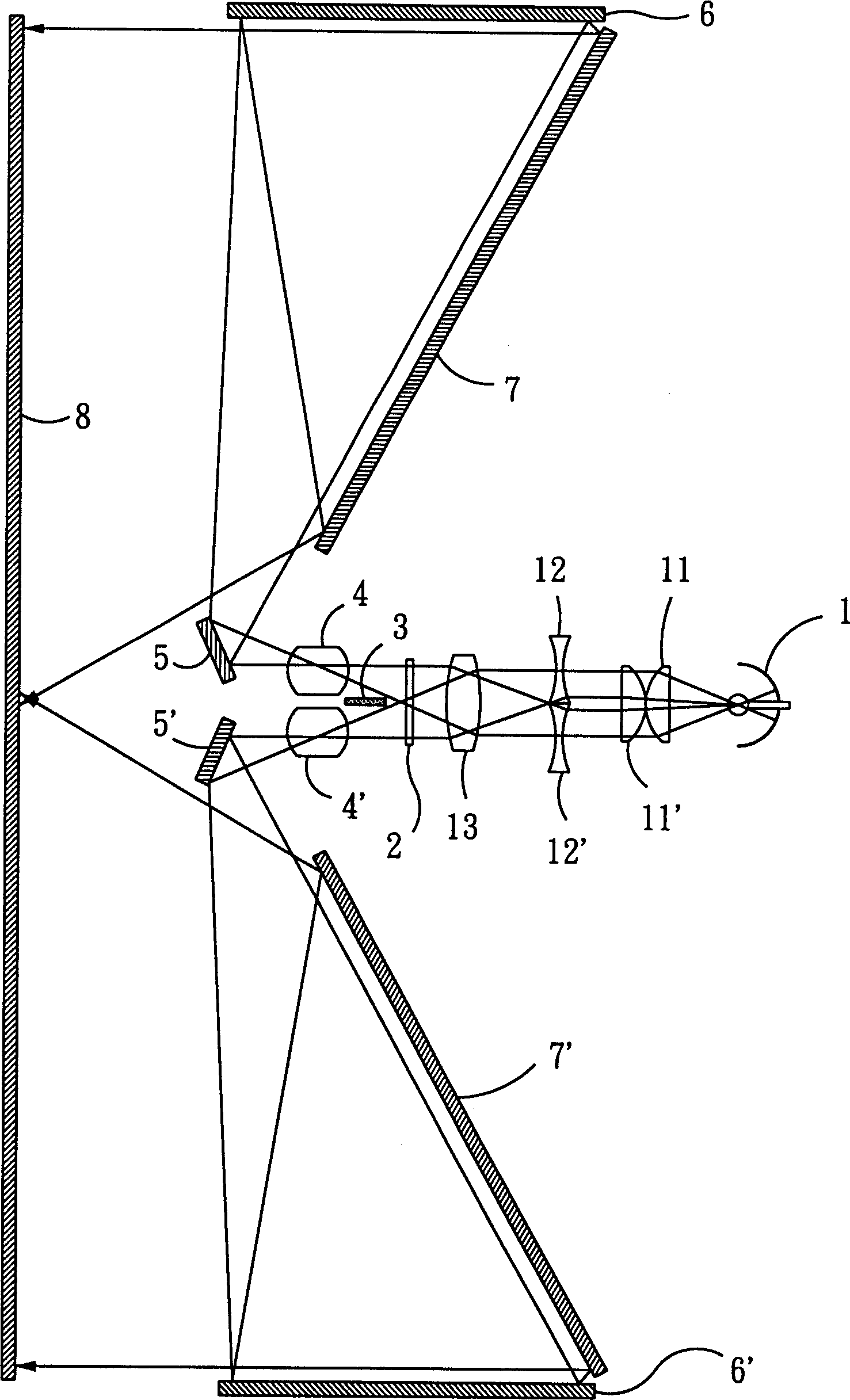
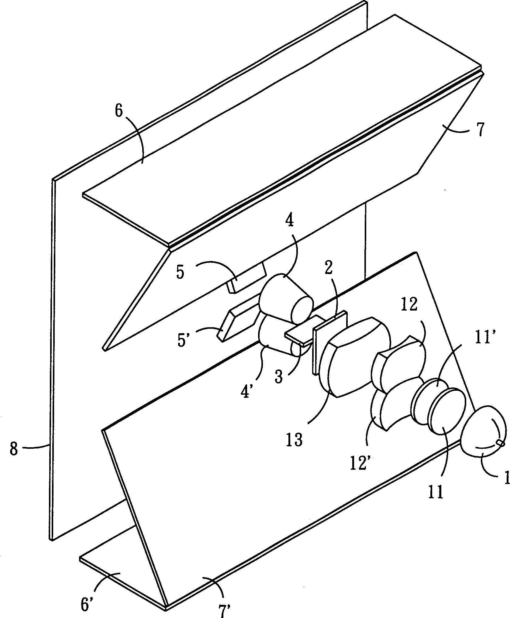
[0024] like figure 1 , 2 As shown, the structure of the present invention can be divided into three parts, one is the projector, the second is the light-returning device, and the third is the screen. The structure, imaging principle and the resulting characteristics are described below:

[0025] 1. Projector: It mainly consists of a bulb light source 1, a set of Condenser Lenses, including lenses 11, 11', 12, 12' and 13, a Video Display 2, a Diaphram 3, and two sets of projection lens groups 4 and 4' placed up and down side by side.

[0026] 2. Light return device: it is mainly composed of upper and lower two groups, each group is composed of three mirrors with opposite mirror surfaces, and the mirror surface of the primary mirror 5 of the upper group has an angle of approximately 120 degrees with the central axis of the projection lens 4 , the secondary mirror 6 is approximately 90 degrees perpendicular to the screen, and has an included angle of approximately 60 degrees wi...


PUM


Abstract

A projection device of a back projection TV is divided into three parts: a projector light return device and a screen, in which, the projector is composed of a dual-light beam projection lens capable of projecting partition pictures and its internal optical components, the light rotation device realizes turning around the projection lights, and the screen for displaying pictures is set in front of the projector. Two reversed picture light beams are projected first from the projector to reach the screen after three times of turnaround reflections by the reflection mirror in the light return device to merge to an amplified picture to save space.

Description

(1) Technical field [0001] The invention relates to a projection device of a rear projection television. (2) Background technology [0002] The structure of the general rear projection TV is mainly composed of a set of three-lens type with three primary colors of red, green and blue separated, or a single-lens type with three primary colors integrated, and then combined with the internal electronic optical developing device, and by means of two mirrors This kind of rear projection TV integrated with the projector and the screen can indeed shorten the projection distance because of the use of reflective lenses, so that the thickness of the TV body is about 100%. Reduce by half to achieve the function of reducing part of the volume. However, with this structure, the projector must be installed below the screen in the fuselage, so that the lower half of the TV itself has to be installed as a large disguised speaker, resulting in a bulky and uncoordinated overall appearance, wh...

Claims


Application Information

Patent Timeline
IPC IPC(8): G02B27/18H04N5/74
Inventor 尤四龙
Owner 尤 四 龙
Why Eureka
Try Eureka