Electronic imaging device

a technology of electronic imaging and imaging body, which is applied in the field of electronic imaging devices, can solve the problems of deterioration of portability, not only portability but also the holding stability of the device, and the main body of the camera tends to become large, and achieves excellent operativeness and a well-balanced whole shap

Inactive Publication Date: 2005-03-10
OLYMPUS OPTICAL CO LTD
View PDF8 Cites 6 Cited by
  • Summary
  • Abstract
  • Description
  • Claims
  • Application Information

AI Technical Summary

Benefits of technology

[0009] An object of the present invention is to provide an electronic imaging device, which can achieve a thin main body of device and maintain well-balanced whole shape and excellent operativeness by considering an arrangement of the internal configuration component.

Problems solved by technology

In general, in an electronic imaging device, especially an electronic camera (digital still camera), since the number of internal element components thereof is larger than that of the camera of the film installation type, the camera main body tends to become large and deteriorate portability, etc.
Especially, when thickness in the optical axis direction of the camera main body becomes thick, the bad influence is caused for not only portability but also the holding stability at shooting.
However, thickness of device is not determined only by a physical size of the shooting optical system.
In addition, it is also possible that portability and the operativeness of the device cannot be satisfied only with the device thin, and convenience worsens oppositely.
Actually, a large restriction is caused in shape and the layout and there is a possibility that the disadvantage is brought up by operativeness etc., since the position of the shooting optical system is limited to a left end or a right end of the main body of the device and as a result, the camera becomes oblong to secure the area of the substrate, etc.
When the shooting optical system is arranged in the end portion in the main body of the device so as not to be overlapped to the various electric circuit board and the image display section, etc., a similar disadvantage is occurred, even when the shooting optical system is incorporated in the main body of the device.

Method used


Image

  • Electronic imaging device
  • Electronic imaging device
  • Electronic imaging device

Examples


first embodiment

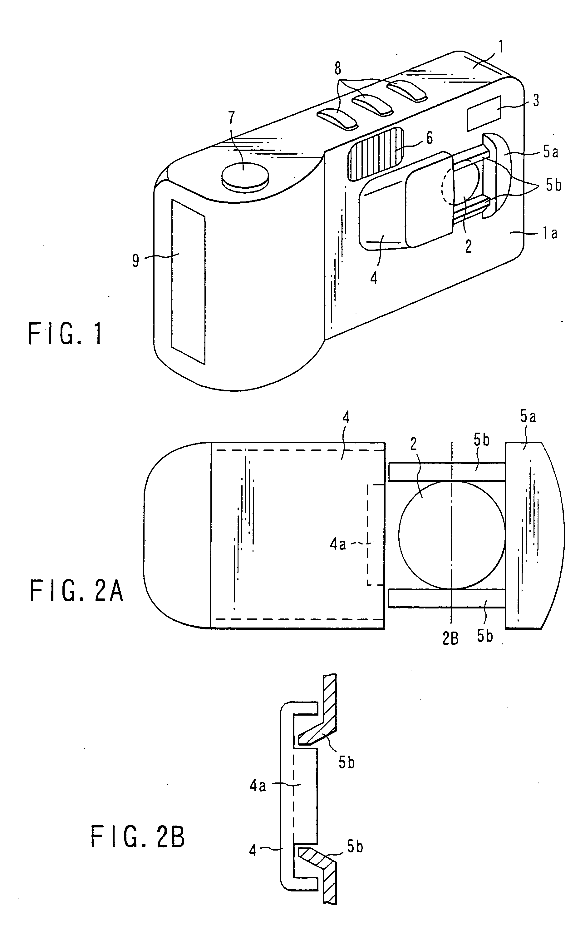
[0066] Next, the embodiments of the present invention will be explained referring to the drawings. FIG. 1 is an external perspective view seen from the front side of an electronic imaging device (hereafter, called as “electronic camera”) according to the present invention.

[0067] In this embodiment, the present invention is applied to an electronic camera, and the right and left direction is made the direction seen from the subject side, when explanation is not clearly described in the following explanations. In FIG. 1, aperture 2 of the shooting lens is arranged in right side of center thereof in front of front cover 1a (exterior section), which protects a front side of main body 1 of the electronic camera. And, a transparent window for optical viewfinder 3 for the subject visual check is arranged at an upper portion of this aperture 2 and at further the right side of camera main body 1, and, in addition, flash window 6 is arranged at the upper portion of the central section.

[0068]...

fourth embodiment

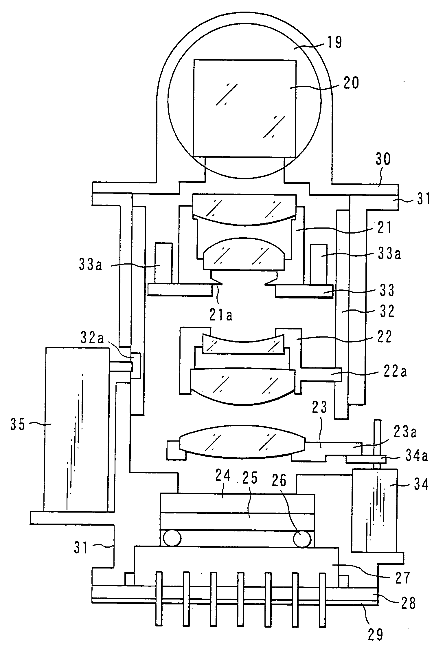
[0110]FIGS. 9 and 10 are a front view, which shows an electronic camera, which builds in the shooting lens device according to the present invention and a side view, which shows externals of the inside of and an electronic camera and shooting lens devices, respectively.

[0111] The shooting lens unit 11A according to this embodiment has roughly the same configuration as shooting lens unit 11 shown in FIG. 6A, but a point that the rear fixation frame 31A further comprises zoom means 97 to perform zooming by moving some of the second group lenses 84a to 84d, differs from shooting lens unit 11 shown in FIG. 6A. Since zoom means 97 is driven, cylindrical rear mirror frame 82 is placed, and motor 98 for the zoom means is set at motor 66 for the iris means and a roughly symmetrical position.

[0112] While assembled for shooting lens unit 11 shown in FIG. 9, AF motor 73a, motor 66 for the squeezing means, and plunger 56 for the shutter means and motor 98 for the zoom means are arranged to pla...

fifth embodiment

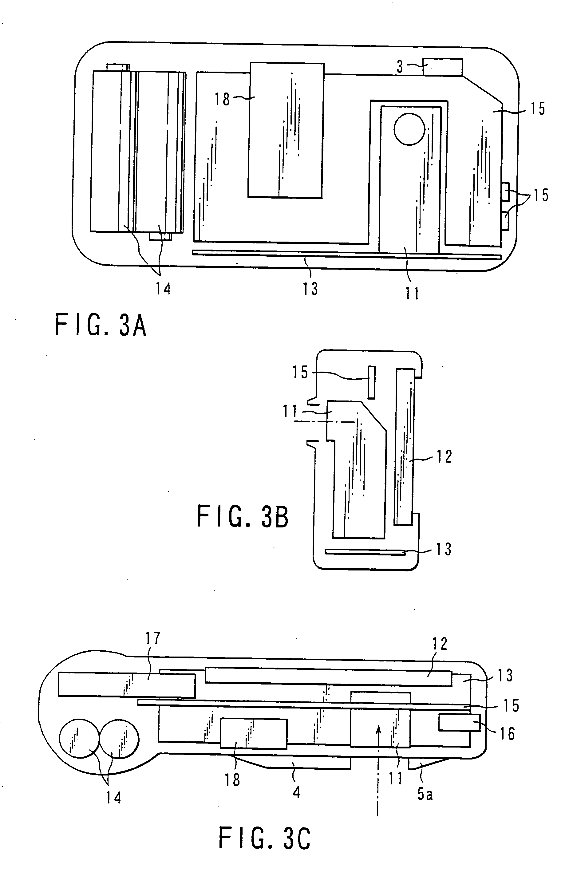
[0114]FIG. 11 is a front view, which shows the shooting lens device for an electronic camera according to the present invention.

[0115] The shooting lens unit 11B according to this embodiment has roughly the same configuration as shooting lens unit 11 shown in FIG. 6A, but a point that plunger 56 for the shutter means is arranged on the other side for reflection mirror 20 with that of shooting lens unit 11 shown in FIG. 6A, is different from shooting lens unit 11 shown in FIG. 6A. That is, AF motor 73a and plunger 56 for the shutter means and motor 66 for the iris means are arranged together on the other side of the planar provided by first optical axis OA1 and second optical axis OA2.

[0116] With such an arrangement of motor, plunger 73a, and 56 and 66, it becomes possible to arrange the control wiring to motor, plunger 73a, 56 and 66, efficiently. However, by such an arrangement of the motor and the plunger, since the entire configuration balance of shooting lens unit 11 collapses,...


PUM


Abstract

An electronic imaging device is provided which includes a first lens group which takes in a luminous flux from a subject along a first optical axis, an optical axis conversion member which bends the luminous flux along a second optical axis which intersects with the first optical axis, a second lens which images the bent luminous flux to an imaging element, and an optical amount adjustment unit provided between the second lens group and the optical axis conversion member. An AF motor, a driving unit which drives the optical amount adjustment unit, and a zoom motor are each selectively arranged at one of four spaces formed by a first plane defined by the optical amount adjustment unit and a second plane defined by the first and second optical axes. The AF motor, the driving unit, and the zoom motor may all be arranged at one side of the second plane.

Description

CROSS-REFERENCE TO RELATED APPLICATIONS [0001] The present application is a divisional application of U.S. application Ser. No. 09 / 618,812, filed Jul. 18, 2000 which claims the benefit of Japanese Patent Application No. 11-248677, filed Sep. 2, 1999, and Japanese Patent Application No. 11-248678, filed Sep. 2, 1999, the contents of which are incorporated herein by this reference.BACKGROUND OF THE INVENTION [0002] The present invention relates to an electronic imaging device, especially, to an electronic imaging device which improves a configuration of a shooting lens unit and an arrangement of an internal unit. [0003] In general, in an electronic imaging device, especially an electronic camera (digital still camera), since the number of internal element components thereof is larger than that of the camera of the film installation type, the camera main body tends to become large and deteriorate portability, etc. Therefore, a lot of proposals to achieve the miniaturization are perform...

Claims


Application Information

Patent Timeline
Patent Type & Authority Applications(United States)
IPC IPC(8): G02B13/00H04N5/225
CPCG02B7/102G02B13/0065G02B13/009H04N2101/00G03B17/17H04N5/2254G03B17/04H04N23/55H04N23/65
Inventor HIGUCHI, TATSUJIDAIGAKU, MASAAKITAKAHASHIASAKURA, YASUOFUJII, NAOKI
Owner OLYMPUS OPTICAL CO LTD
Why Eureka
Try Eureka