
Tandem incubator for clinical analyzer

A clinical analysis and incubator technology, applied in analytical materials, biological material analysis, instruments, etc., can solve problems affecting the total processing capacity of equipment, and achieve the effect of simplifying the device and reducing costs

Inactive Publication Date: 2004-01-07
ORTHO-CLINICAL DIAGNOSTICS
View PDF7 Cites 2 Cited by
  • Summary
  • Abstract
  • Description
  • Claims
  • Application Information

AI Technical Summary

Problems solved by technology

Therefore, the scheduling of testing for multiple types of patient samples must significantly affect the overall throughput of the facility

Method used

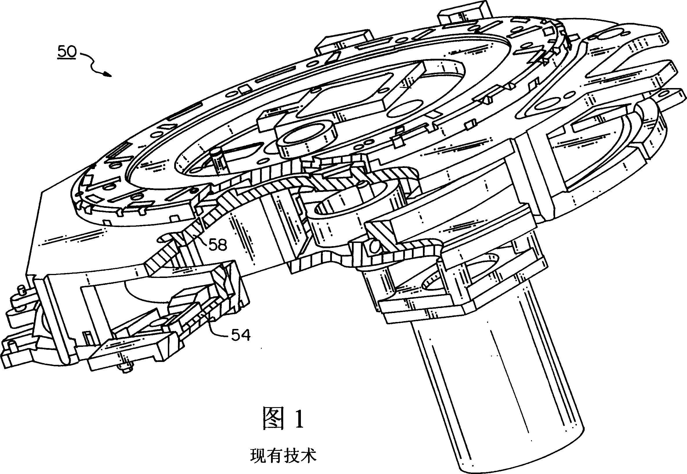
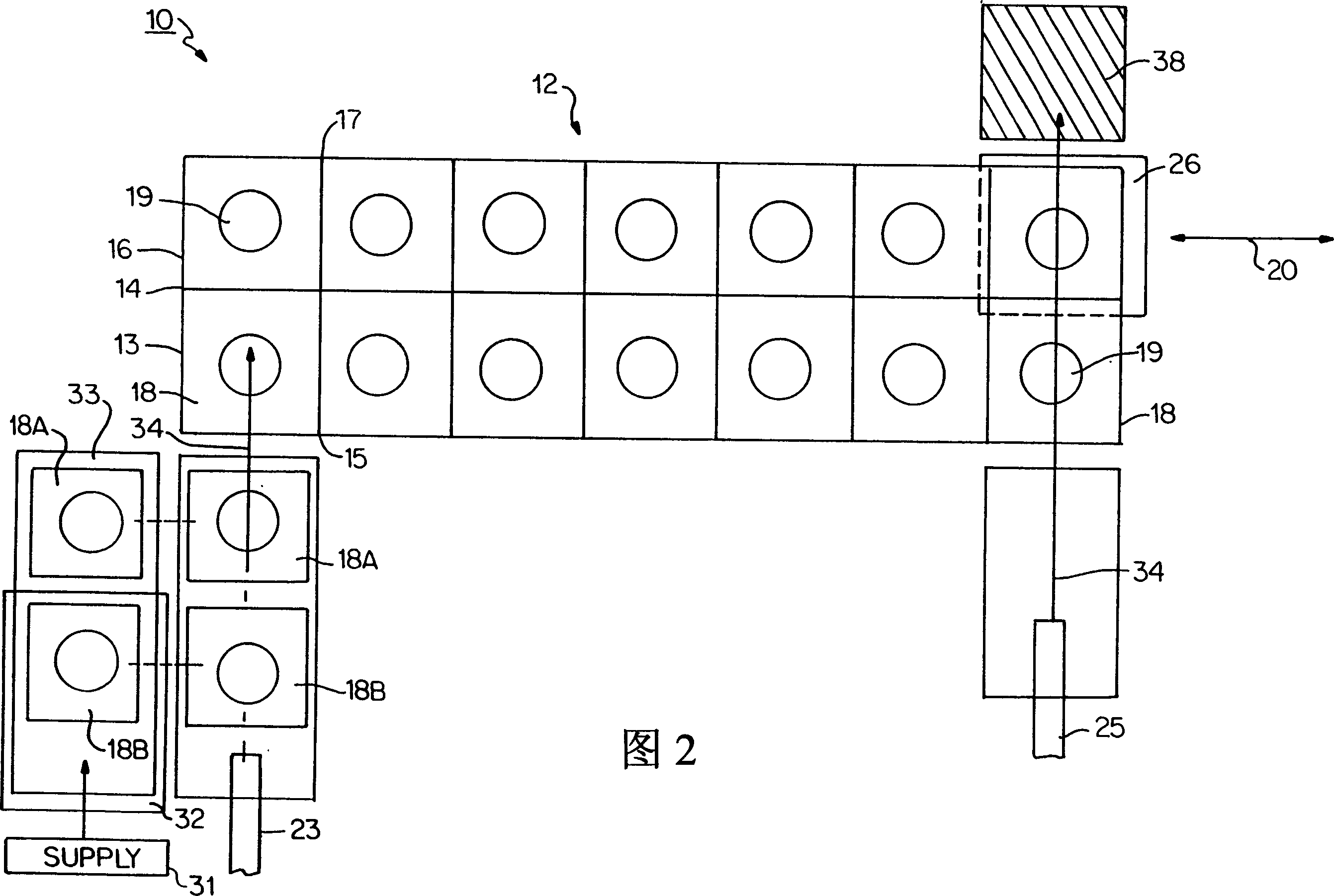
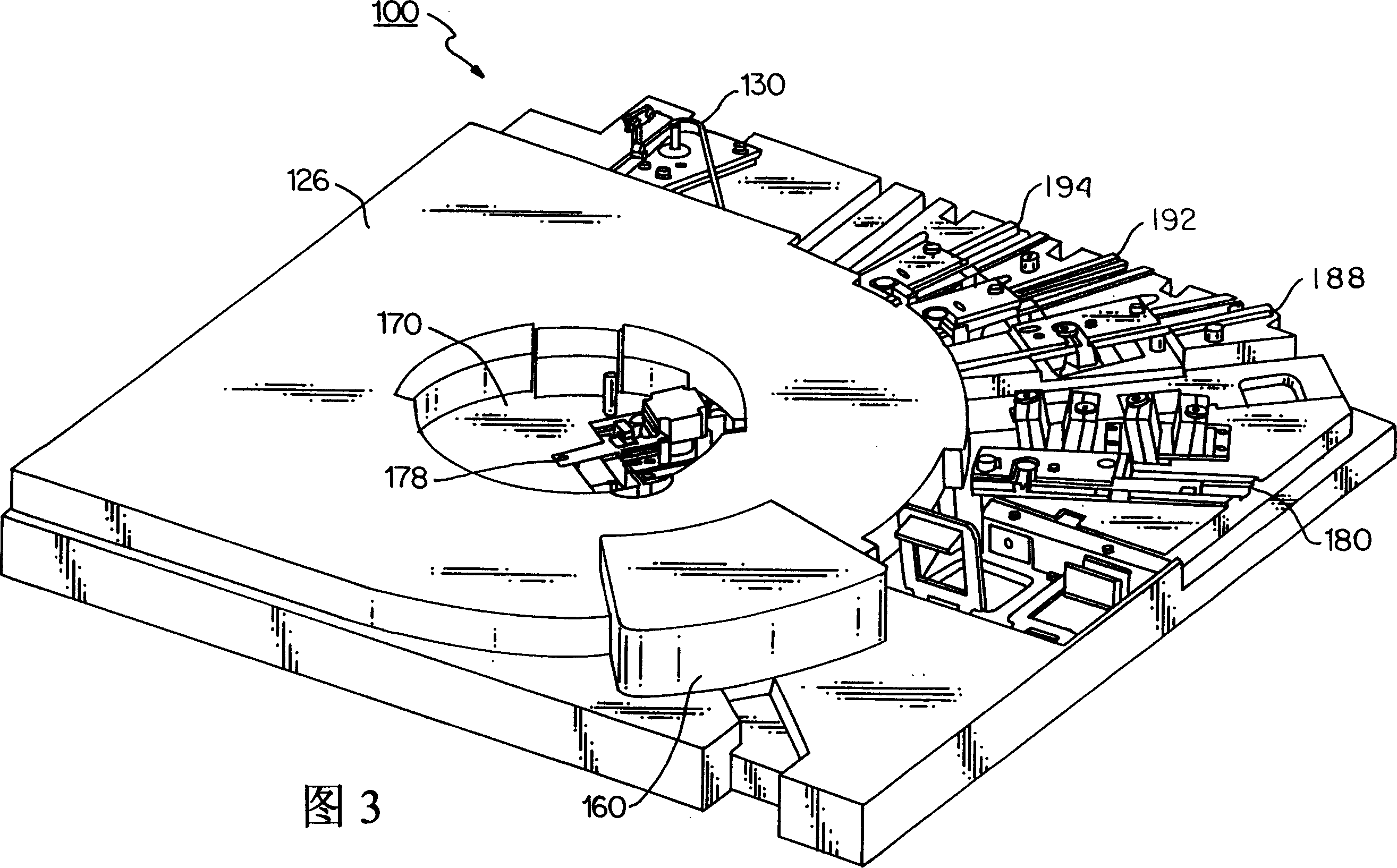

Image

  • Tandem incubator for clinical analyzer
  • Tandem incubator for clinical analyzer
  • Tandem incubator for clinical analyzer

Examples


Embodiment Construction

[0040] The following description refers to a specific embodiment of a sequential loading incubator made in accordance with the present invention. In the course of the description, specific terms such as "inner," "outer," "lateral," "vertical," "horizontal," "upper," "lower," and similar terms are used in connection with the drawings to provide a frame of reference. However, these terms (unless indicated otherwise) should not be construed as limiting this invention.

[0041]In the discussion, the term "element" is used in connection with a sample. As defined herein, this term refers to dry slides as well as any other form of sample container. It will be readily appreciated that the present invention addresses advantageous positioning (rotary, linear or otherwise) of the container in an incubator to enhance throughput.

[0042] In order to clarify the background of the present invention and simplify the following description, the following mainly refers to a "dry" incubator fo...


PUM


Abstract

An incubator includes an incubator ring assembly having at least two concentric rings supported for rotation about a common axle defining an axis of rotation. Each concentric ring includes a plurality of circumferentially defined load positions, each load position being sized for accommodating a test sample. At least one test station is arranged in relation to the plurality of load positions to selectively test a test sample, the test samples being are sequentially shuttled into and out of load positions of at least one of the concentric rings to increase the overall throughput of the analyzer.

Description

technical field [0001] The invention relates to the field of analysis sample testing, in particular to a sequential serial incubator for clinical analyzers. Background technique [0002] Clinical analyzers typically include at least one incubator for patient sample processing. For example, a typical "dry" chemical incubator is defined by a rotor assembly comprising a single rotatable drive ring with a plurality of circumferentially arranged loading stages. Each loading station is sized to accommodate a dry element on which a number of patient samples can be measured. [0003] According to at least one type of dry-type incubator, the slide element is provided one at a time to the measuring station adjoining the incubator. After the measurement of the sample flow is completed, the slide element is shuttled or introduced into one of the empty loading stations of the incubator, for example by using reciprocating propeller blades as the rotor assembly, to advance the next empty...

Claims


Application Information

Patent Timeline
Patent Type & Authority Applications(China)
IPC IPC(8): G01N35/04G01N35/00G01N35/02
CPCG01N2035/00356Y10T436/11Y10T436/113332Y10T436/114165G01N2035/0455G01N35/00029Y10T436/119163Y10T436/114998G01N35/025G01N2035/00039G01N35/00
Inventor R·F·雅库博维奇G·S·哈特曼J·J·波特
Owner ORTHO-CLINICAL DIAGNOSTICS
Learn More