Punch

The technology of a puncher and a hole shaft, which is applied in the field of punchers

Inactive Publication Date: 2004-01-14
KOKUYO CO LTD
View PDF0 Cites 2 Cited by
  • Summary
  • Abstract
  • Description
  • Claims
  • Application Information

AI Technical Summary

Problems solved by technology

However, if this is done, the problem of the accumulation of punch chips in the chip box cannot be grasped from the f...

Method used


Image

  • Punch
  • Punch
  • Punch

Examples


Embodiment Construction

[0021] Hereinafter, an embodiment of the present invention will be described with reference to the drawings.

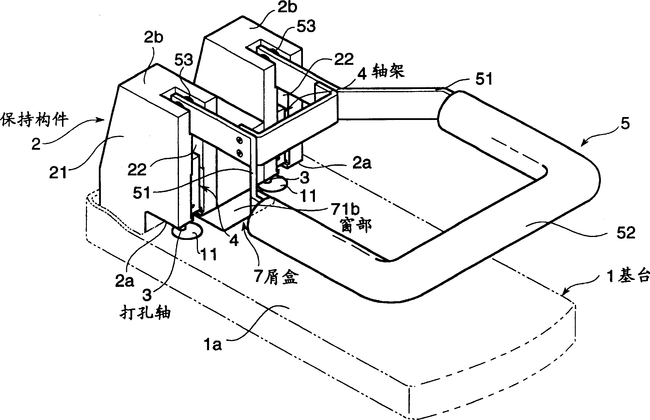
[0022] The punch of this embodiment, in figure 1 Shows the state in which the cover C described later is removed, and it includes: a base 1, a holding member 2 standing up from the upper end of the base 1, and a punching shaft that is housed in the holding member 2 so as to be lifted and lowered. The pedestal 4 of 3, the operating handle 5 whose base end is supported on the upper end side of the holding member 2 to be rotatable, and in the holding member 2, the lifting action of the pedestal 4 is linked with the rotating operation of the operating handle 5 Linkage mechanism 6 (refer to Figure 6 ).

[0023] The base 1 is a plate-shaped member with sufficient rigidity to support the holding member 2 and the operating handle 5 as its appendage. The upper surface is used as the paper placement surface 1a, and at the same time, the punch shaft 3 near the upper end corresponds...


PUM


Abstract

Provided is a punch wherein a stag condition of punched chips is simply and precisely grasped when paper sheets are put on a base stand by solving conventional defects in which an accommodation condition of the punched chips has to be recognized from a back face side of the punch. This punch comprises a base stand 1; a holding mechanism 2 integrally standing from a top end side of the base stand 1; and a shaft holder 4 elevatably accommodated in the holding mechanism 2 and holding a punching shaft 3. At a position forming a part of the base stand 1, a window part 72b allowing the housing condition of the punched chips to be seen from the base stand 1 side is installed.

Description

Technical field [0001] The present invention relates to a puncher for punching a plurality of sheets of paper, and relates to the ability to easily discard the puncher scraps accumulated in a scrap box while the storage state of the puncher scraps can be grasped from the front side of the puncher Puncher. Background technique [0002] In the past, in order to bind documents, a hole punch for opening one, two or more holes along its binding side edge is known. Among them, the so-called powerful hole punch is a punch that can punch more than 100 sheets of paper. Its structure is that the punch shaft is hollow, and the cut punch paper scraps Sequentially taken into the hollow part, the punch scraps can be contained in a scrap box integrally provided on a part of the powerful punch. [0003] However, because this kind of hole punch is integrated with the chip box, when throwing away the hole punch chip in the chip box, the whole hole punch must be lifted at once, which is very inconv...

Claims


Application Information

Patent Timeline
IPC IPC(8): B26F1/32
Inventor 古川胜章
Owner KOKUYO CO LTD
Why Eureka
Try Eureka