Connector

A technology of connectors and terminal joints, applied in the field of connectors, to achieve the effects of enhanced locking force, improved operability, and high strength

Inactive Publication Date: 2004-01-14
SUMITOMO WIRING SYST LTD
View PDF1 Cites 6 Cited by
  • Summary
  • Abstract
  • Description
  • Claims
  • Application Information

AI Technical Summary

Problems solved by technology

However, because the locking surface 5 is inclined forward toward its upper end (relative to the rear end of the deformation direction), and the displacement locus of the locking surface 5 during the elastic deformation is smaller than that of Figure 17 The middle is more forward, so when the locking portion 4 is elastically deformed, the locking surface 5 is more likely to interfere with the edge of the locking hole 2a

Method used


Image

  • Connector
  • Connector
  • Connector

Examples


Embodiment Construction

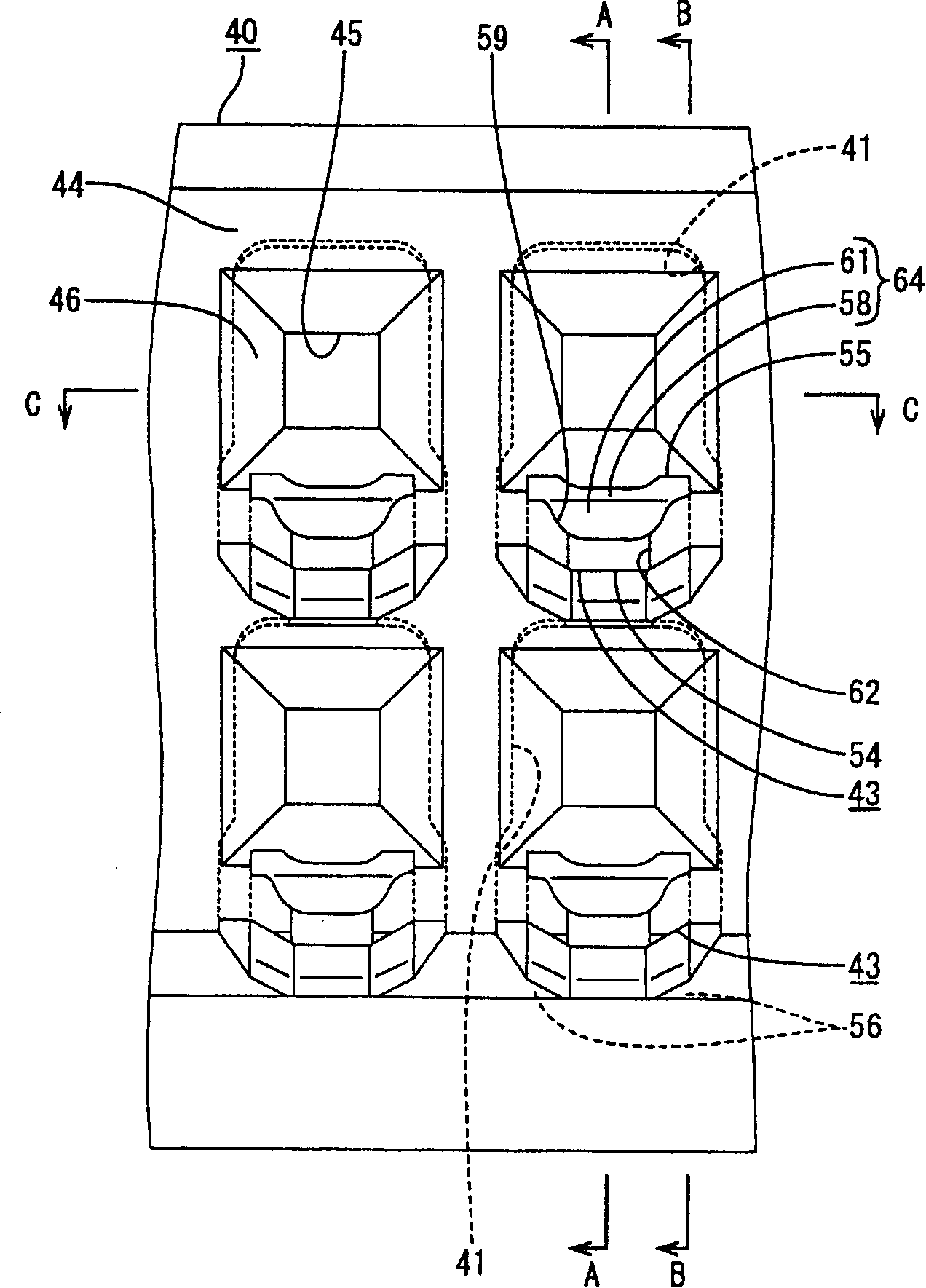
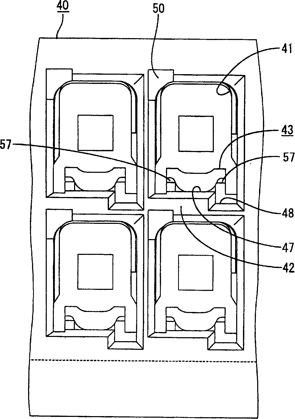
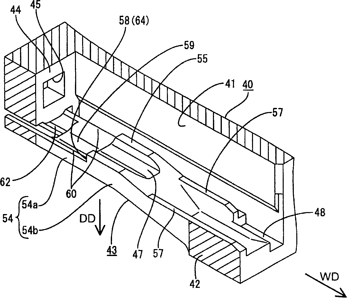
[0044] refer to Figures 1 to 1 6 describes a preferred embodiment of the present invention. In this embodiment, a female connector is shown in which one or more female terminal fittings 10 are at least partially inserted into a female connector housing 40 (hereinafter simply referred to as "female housing 40"). When at least partially housed in a female housing 40, the female terminal fitting 10 is electrically connectable to a male terminal fitting at least partially housed in a mating male housing (neither the male terminal fitting nor the male housing is shown), The male housing will be connected to the female housing 40 . In the following description, the directions 1WD in which the female terminal fitting 10 is inserted into the female housing 40 and withdrawn from the female housing 40 are referred to as the forward direction and the rearward direction, respectively, while reference is made to the vertical direction. Figure 7 .

[0045] The female terminal fitting 1...


PUM


Abstract

A connector has a housing (40) with cavities (41) and resiliently deformable locks (43) that project into the cavities (41). Terminal fittings (10) are insertable into the cavities (41) and deform the locks (43) in a deforming direction (DD) that intersects the inserting and withdrawing directions (IWD) of the terminal fitting (10). The locks (43) then restore and locking surfaces (64) of the locks (43) lock the terminal fittings (10) in the cavities (41). Each locking surface (64) has an upper locking surface (58) furthest into the cavity (41) and a lower locking surface (61). The lower locking surface (61) is at an obtuse angle to the withdrawing direction of the terminal fitting (10), whereas an angle of the upper locking surface (58) to the withdrawing direction is smaller than the angle of the lower locking surface (61).

Description

technical field [0001] The invention relates to a connector. Background technique [0002] An example of a connector is known from Japanese Unexamined Patent Publication No. 4-115475 in which terminal fittings are locked by locking portions in the connector housing. Provided in the connector housing 1 of this connector are cavities 3 into which terminal fittings 2 can be inserted from behind, and at the bottom surface of each cavity 3 are provided locking portions 4 which can be elastically engages with the inserted terminal fitting 2 so as to lock the terminal fitting 2, such as Figure 17 shown. The locking portion 4 includes an arm 4a that is elastically deformable in the vertical direction and a fixing protrusion 4b that protrudes from the upper surface of the arm 4a and is engageable with a groove formed in the bottom wall of the terminal fitting 2. Keep the hole 2a engaged so as to engage the edge of the hole 2a. [0003] When the above-mentioned connector is miniat...

Claims


Application Information

Patent Timeline
Patent Type & Authority Applications(China)
IPC IPC(8): H01R13/11H01R13/422H01R13/436
CPCH01R13/4223H01R13/114H01R13/111H01R13/4362
Inventor 中村英人石川亮太郎川濑治南光勇一栗本直哉
Owner SUMITOMO WIRING SYST LTD
Why Eureka
Try Eureka