Space on-track repeated locking and releasing mechanism

A technique for repeatedly locking and releasing mechanisms, applied in mechanical equipment, fixtures, etc., can solve the problems of non-reusable use and excessive impact, and achieve the effect of simple structure, small impact, and no influence on attitude and stability control

Active Publication Date: 2012-10-10
HARBIN INST OF TECH
View PDF6 Cites 11 Cited by
  • Summary
  • Abstract
  • Description
  • Claims
  • Application Information

AI Technical Summary

Problems solved by technology

In my country, although many technical achievements and engineering applications have been made in the field of spacecraft connection and separation mechanisms in recent years, the research on large-load low-impact repetitive locking and releasing mechanisms for on-orbit applications has not yet been carried out, and the existing locks The tight release mechanism is not reusable and has the problem of excessive shock during release

Method used


Image

  • Space on-track repeated locking and releasing mechanism
  • Space on-track repeated locking and releasing mechanism
  • Space on-track repeated locking and releasing mechanism

Examples


specific Embodiment approach 1

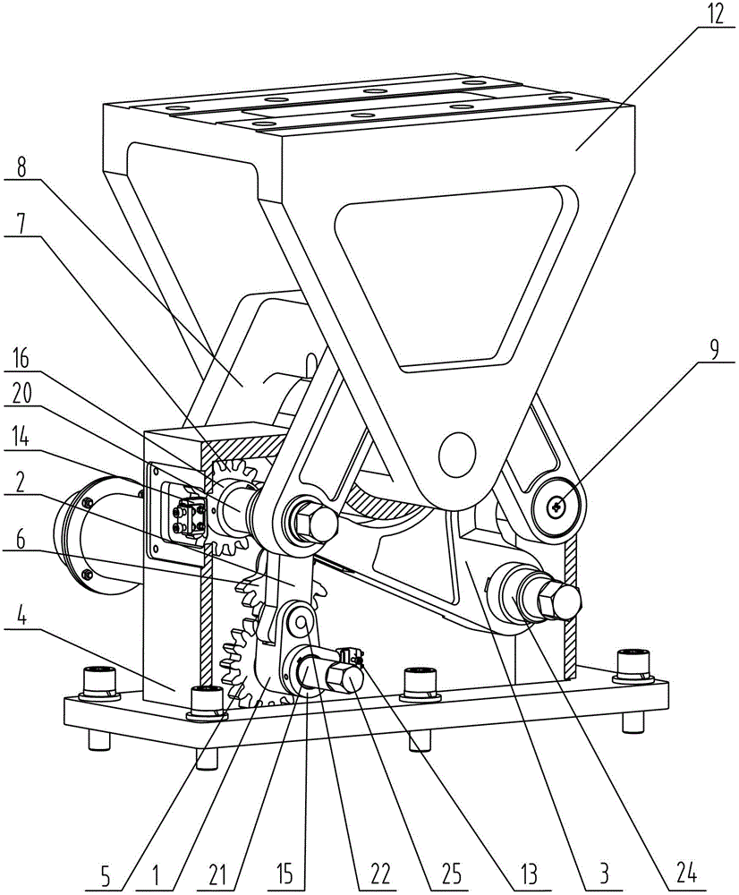
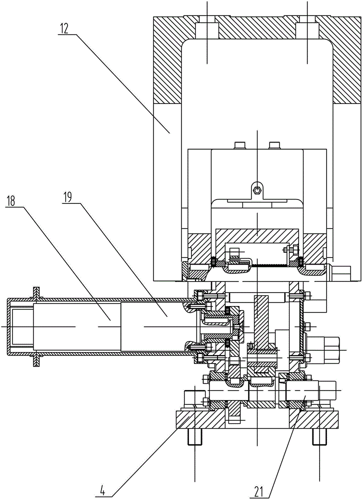
[0014] Specific implementation mode one: combine Figure 1-Figure 3 Describe this embodiment. A space-on-orbit repetitive locking and releasing mechanism in this embodiment includes a locking trunnion mechanism, a compression hook mechanism, a locking base mechanism, a crank rocker mechanism, and a drive gear mechanism. The locking trunnion The mechanism is arranged on the upper end of the locking base mechanism, and the driving gear mechanism is respectively connected with the locking hook mechanism and the crank rocker mechanism.

[0015] The locking base mechanism includes a base 4, the upper end of the base 4 is provided with a V-shaped groove, and the middle part of the base 4 is provided with a mechanism accommodating cavity,

[0016] The locking trunnion mechanism includes a trunnion 12, and the lower end of the trunnion 12 is arranged in a V-shaped groove on the base 4,

[0017] Described pressing lock hook mechanism comprises lock hook gear 7, lock hook body 8, first...

specific Embodiment approach 2

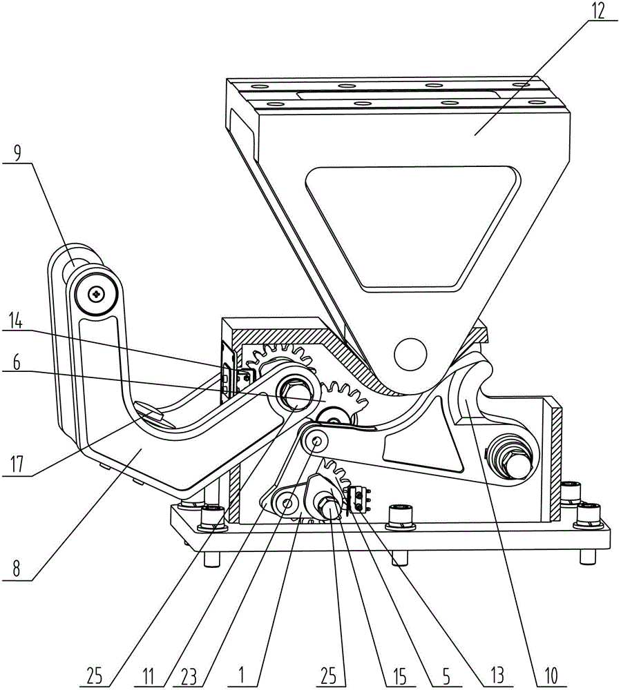
[0025] Specific implementation mode two: combination figure 2 Referring to this embodiment, the compression lock hook mechanism of this embodiment further includes a pressure sensor 17, which is arranged on the lock hook body 8, and is used to measure the pressure of the locking state. Such setting is convenient for controlling whether the lock hook body 8 is locked. Other compositions and connections are the same as in the first embodiment.

specific Embodiment approach 3

[0026] Specific implementation mode three: combination figure 1 with figure 2 To illustrate this embodiment, the crank-rocker mechanism of this embodiment further includes a limiting device 11 , and the limiting device 11 is fixedly mounted on the connecting rod 2 . Such setting limits the extreme positions of the main crank rod 1 and the connecting rod 2 . Other compositions and connections are the same as those in Embodiment 1 or Embodiment 2.


PUM


Abstract

The invention discloses a space on-track repeated locking and releasing mechanism, relating to a repeated locking and releasing mechanism. The invention aims to solve the problem in on-track repeated locking and releasing of large payload on spacecraft. The mechanism comprises a locking trunnion mechanism, a compaction lock hook mechanism, a locking base mechanism, a crank-rocker mechanism and a drive gear mechanism, wherein the locking trunnion mechanism is arranged at the upper end of the locking base mechanism; and the drive gear mechanism is connected with the compaction lock hook mechanism and the crank-rocker mechanism respectively. In the invention, the locking trunnion mechanism, the compaction lock hook mechanism, the locking base mechanism, the crank-rocker mechanism and the drive gear mechanism are crossed, the structure is simple and compact, all degrees of freedom of the fixed object can be completely limited, the repeated locking can be realized, the operability is good, and the using requirement of on-track locking-releasing-locking can be met. The mechanism disclosed by the invention is applicable to the technical field of aerospace and mechatronics.

Description

technical field [0001] The invention relates to a repetitive locking and releasing mechanism, in particular to a space-on-rail repetitive locking and releasing mechanism. Background technique [0002] In the field of aerospace, pyrotechnic devices such as explosive bolts and pyrotechnic cutters are mostly used for the connection and separation of spacecraft and payloads. Although they have the characteristics of simple structure and high reliability, they cannot achieve the function of repeated locking on orbit. The huge impact generated by the separation has a serious impact on the attitude and precision control of the space manipulation platform. [0003] In recent years, with the development of space station construction and space detection technology, the space-to-earth shuttle system has an increasingly strong demand for locking-release-relocking of transported large-scale and heavy-duty materials, and various space control platforms are released in orbit without impact...

Claims


Application Information

Patent Timeline
Patent Type & Authority Applications(China)
IPC IPC(8): F16B1/04
Inventor 岳洪浩王宇兵祝洪滨邓宗全
Owner HARBIN INST OF TECH
Why Eureka
Try Eureka