Chromatic aberration corrector for charged particles and charged-particle optical apparatus using the corrector

a charged particle and optical apparatus technology, applied in the direction of instruments, mass spectrometers, beam deviation/focusing by electric/magnetic means, etc., can solve the problem that the expected aberration correction effect cannot be sufficiently obtained, the aberration correction cannot be realized in reality, and it is difficult to adjust the aberration correction for arbitrary optical conditions. , to achieve the effect of stabilizing chromatic aberration correction, avoiding aberration, and improving chromatic aberration correction accuracy

Active Publication Date: 2007-05-01
HITACHI HIGH-TECH CORP
View PDF3 Cites 12 Cited by
  • Summary
  • Abstract
  • Description
  • Claims
  • Application Information

AI Technical Summary

Benefits of technology

[0022]There is no independent adjusting means in the aberration corrector, which significantly limits the free degree in use and design.
[0026]According to the present invention, under the condition other than the optical conditions optimized in the design of the corrector, the focus adjusting function incorporated into the aberration corrector can make re-adjustment so as to be adapted to the aberration correction conditions (i) to (iv) and suitably perform aberration correction. For instance, when changing the crossover position of a condenser lens to choose a probe current in SEM, optimal aberration correction can be always found, since adjustable parameters can be additionally obtained by the present invention. Higher-order optimal aberration correction conditions which have not been obtained only by the free degree in prior art corrector will be also attainable. Examples of the latter, while satisfying the chromatic aberration correction conditions, include setting of a condition for preventing high-order aberration such as second-order chromatic aberration and fifth-order aperture aberration and setting of a condition for stabilizing chromatic aberration correction against power source instability.
[0027]The present invention can be realized by the corrector alone by integrating the aberration correction function with the focus adjusting function. The optical adjustment of the corrector can be made independently of other optical elements such as a condenser lens and an objective lens. When adjusting the crossover position of the corrector, the prior art construction must make adjustment in engagement with the condenser lens. The present invention in which the corrector itself has the focus adjusting function can make the above-described adjustment by the corrector alone without touching the condenser lens. The construction of the aberration corrector of this invention also has the merit that the axis alignment accuracy is easily obtained in design and manufacturing.

Problems solved by technology

Moreover, depending on the incident condition, β1 to β4 satisfying the trajectory conditions (i) to (iv) are not found in principle, or if they are found, they might be excessive in an applied voltage and magnetic excitation so that aberration correction cannot be realized in reality.
Therefore, it was difficult to adjust the aberration corrector for arbitrary optical conditions such as incident conditions.
In some case, an expected aberration correction effect cannot be sufficiently obtained.
When the number of limitations in design is increased, it is more difficult to satisfy them at the same time.

Method used


Image

  • Chromatic aberration corrector for charged particles and charged-particle optical apparatus using the corrector
  • Chromatic aberration corrector for charged particles and charged-particle optical apparatus using the corrector
  • Chromatic aberration corrector for charged particles and charged-particle optical apparatus using the corrector

Examples


embodiment 1

[0035]An embodiment will be described below with the drawings.

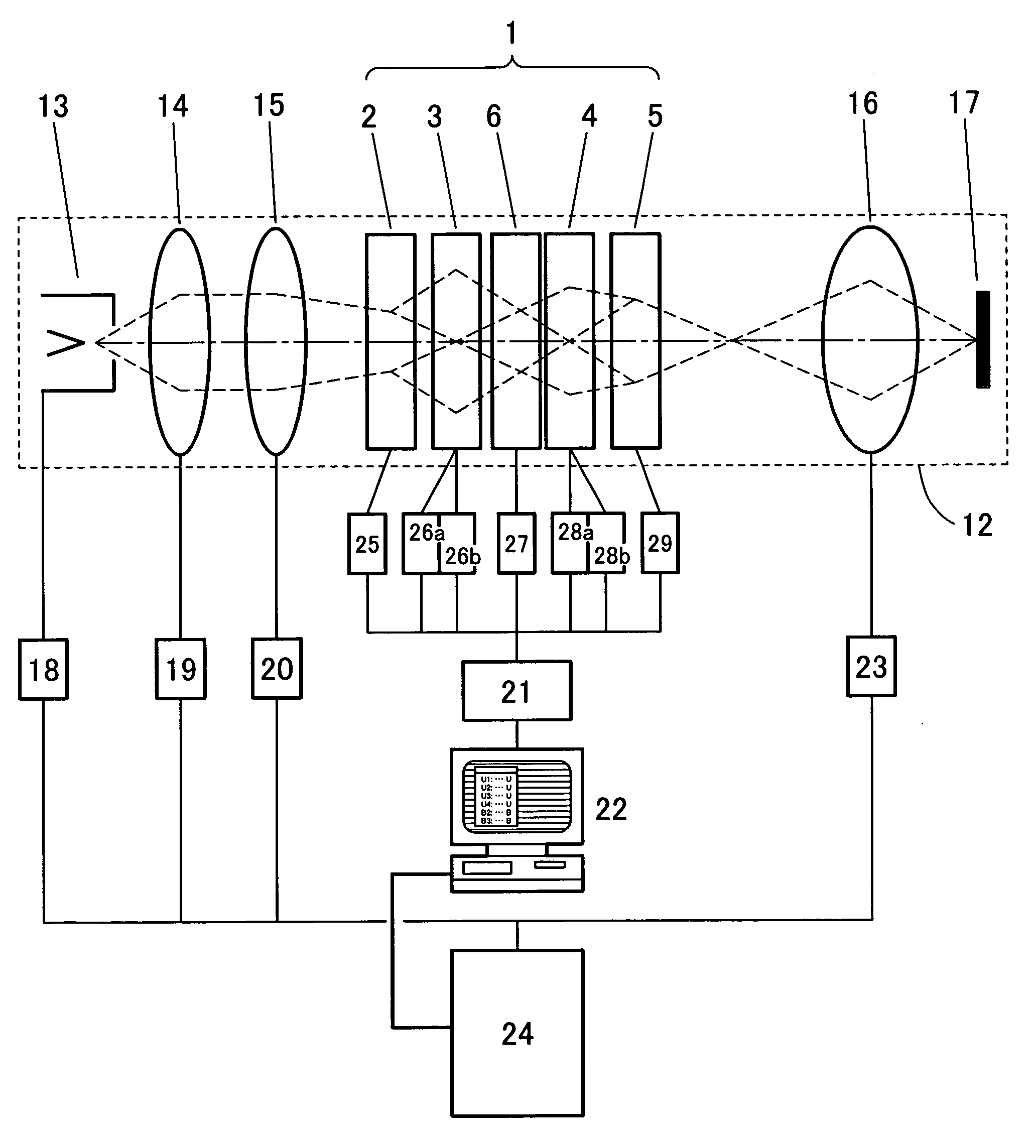
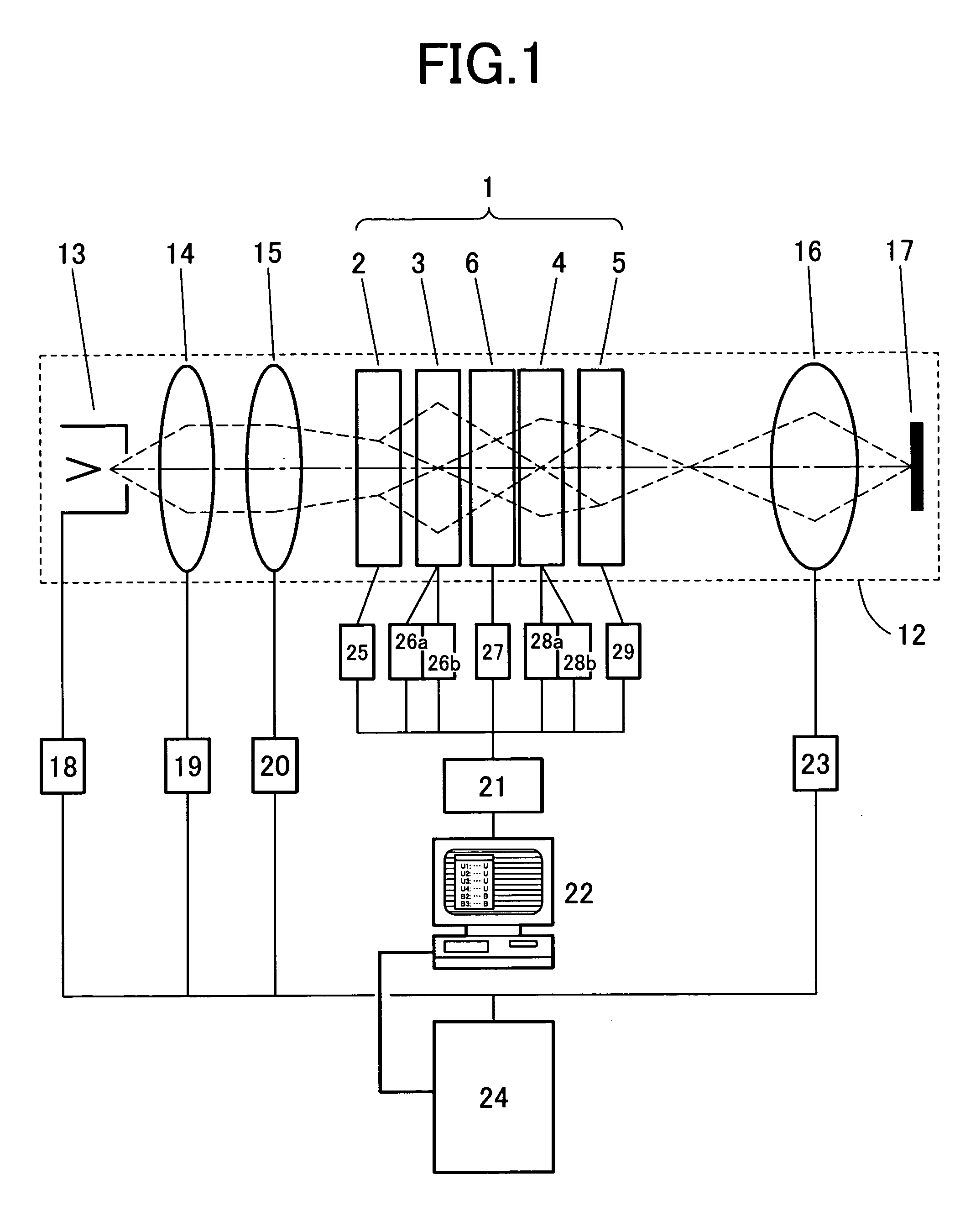
[0036]FIG. 1 shows an embodiment of an SEM. FIG. 1 includes main elements of an electron optics system of the SEM. An electron beam emitted from an electron source 13, after adjustment of the amount of a beam current by condenser lenses 14 and 15, forms a crossover in the position suitable for an objective lens 16. This beam crossover is demagnified and projected onto a sample surface 17 by the objective lens 16 to be a beam probe. The beam probe is scanned on the sample surface by deflector coils, not shown, to produce secondary electrons owing to the electron beam illumination. By measuring the amount of the secondary electrons in positions on the sample surface, “scanning electron microscope image (SEM image)” is thereby obtained. Apparatus and devices which are not important in the description of the present invention, such as a secondary electron detector, a sample stage holding a sample, and aperture apparatus to li...

embodiment 2

[0051]FIG. 5 shows a constructional example different from FIG. 3. The 12 poles 3 and 4 in the second and third stages and the intermediate potential electrodes are used together to apply the intermediate potential Vm added to the potential for multipole field formation. The space between the second and third stages of the multipole lenses becomes an intermediate potential region. In FIG. 5, the voltage sources 26, 28, and 27 are connected in series to superimposed intermediate potentials on multipole potentials.

[0052]FIG. 6 shows results obtained by simulating changes in trajectories in the corrector when the intermediate potential is varied. In the simulation, the incident condition to the corrector is fixed, and rectangle-like distribution of electrical potentials and quadrupole field strengths are assumed. The numerals 7a, 7b and 7c denote an x trajectory and the numerals 8a, 8b and 8c denote a y trajectory. The calculation conditions to a, b and c are summarized in Table 1. A c...

embodiment 3

[0054]In Embodiments 1 and 2, the multipole lenses are assembled in four stages and the intermediate potential region is formed between the inner multipole lenses. However, the intermediate potential region may be formed in a space between other stages or in a plurality of spaces between the stages, not between the multipole lenses arranged in the center.

[0055]In Embodiments 1 and 2, the intermediate potential region 6 is formed only in the space between the stages of the second-stage multipole lens 3 and the third-stage multiple lens 4. In the constructional example shown in FIG. 7, the intermediate potential regions are provided in all three spaces between the stages of the 1-2 (6A), 2-3 (6B), and 3-4 (6C). Such a plurality of intermediate potential regions can be realized by providing the intermediate potential electrode structures 6a, 6b, 6c and 6d of FIG. 3 in the spaces between the stages of the multipole lenses, respectively.

[0056]The intermediate potentials are supplied from...


PUM


Abstract

The present invention provides an aberration corrector functioning under a condition outside the setting optical condition of an incorporated charged particle beam apparatus.An intermediate potential region different from the ground potential of an aberration corrector is provided in the space between the stages of multipole lenses constructing the aberration corrector to adjust a potential. Using this, when selecting an incident (outgoing) condition, an outgoing (incident) condition can be adjusted.

Description

CLAIM OF PRIORITY[0001]The present invention claims priority from Japanese application JP 2003-387360 field on Nov. 18, 2003, the content of which is hereby incorporated by reference on to this application.BACKGROUND OF THE INVENTION[0002]The present invention relates to a technique for minimizing the beam spot diameter of a charged particle beam apparatus. More specifically, the present invention relates to an aberration corrector with lenses in multiple stages including multipole lenses, which is used in a charged particle beam microscope apparatus including a scanning electron microscope.[0003]In a charged-particle optical apparatus including electron microscopes such as a scanning electron microscope (SEM) and a transmission electron microscope (TEM), a lens using an electric field or a magnetic field to condense a charged particle beam is essential. In a rotational symmetrical lens generally used as the electromagnetic lens, chromatic aberration and aperture aberration such as ...

Claims


Application Information

Patent Timeline
Patent Type & Authority Patents(United States)
IPC IPC(8): G21K1/08G21K7/00G21K5/04H01J37/12H01J37/14H01J37/145H01J37/153
CPCH01J37/153
Inventor YOSHIDA, TAKAHOKAWASAKI, TAKESHI
Owner HITACHI HIGH-TECH CORP
Why Eureka
Try Eureka