Combined machining hydraulic locking power tool table

A technology of compound processing and power tool holder, which is applied in the direction of metal processing equipment, metal processing machine parts, tool holders, etc., can solve the problems of complex structure and high cost of power tool holder, and achieve simple structure, complete functions and large locking force Effect

Active Publication Date: 2014-12-10
ZHEJIANG RIFA PRECISION MACHINERY
View PDF6 Cites 11 Cited by
  • Summary
  • Abstract
  • Description
  • Claims
  • Application Information

AI Technical Summary

Problems solved by technology

[0003] The purpose of the present invention is to solve the defects of complex structure and high cost of the existing power tool table, and to provide a hydraulic locking power tool table with relatively simple and compact mechanism and complete functions for composite processing

Method used


Image

  • Combined machining hydraulic locking power tool table
  • Combined machining hydraulic locking power tool table
  • Combined machining hydraulic locking power tool table

Examples


Embodiment Construction

[0022] Specific embodiments of the present invention will be described in detail below in conjunction with the accompanying drawings.

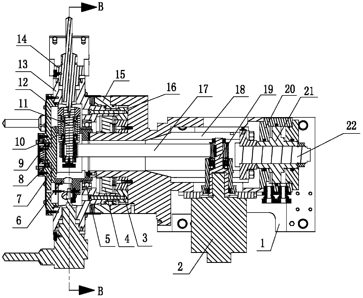
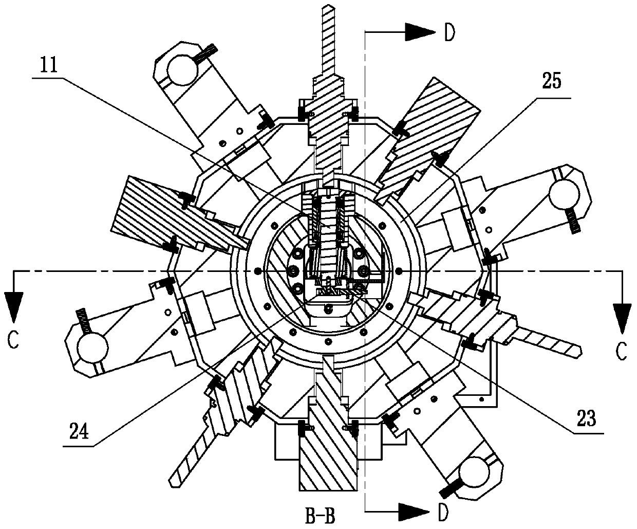
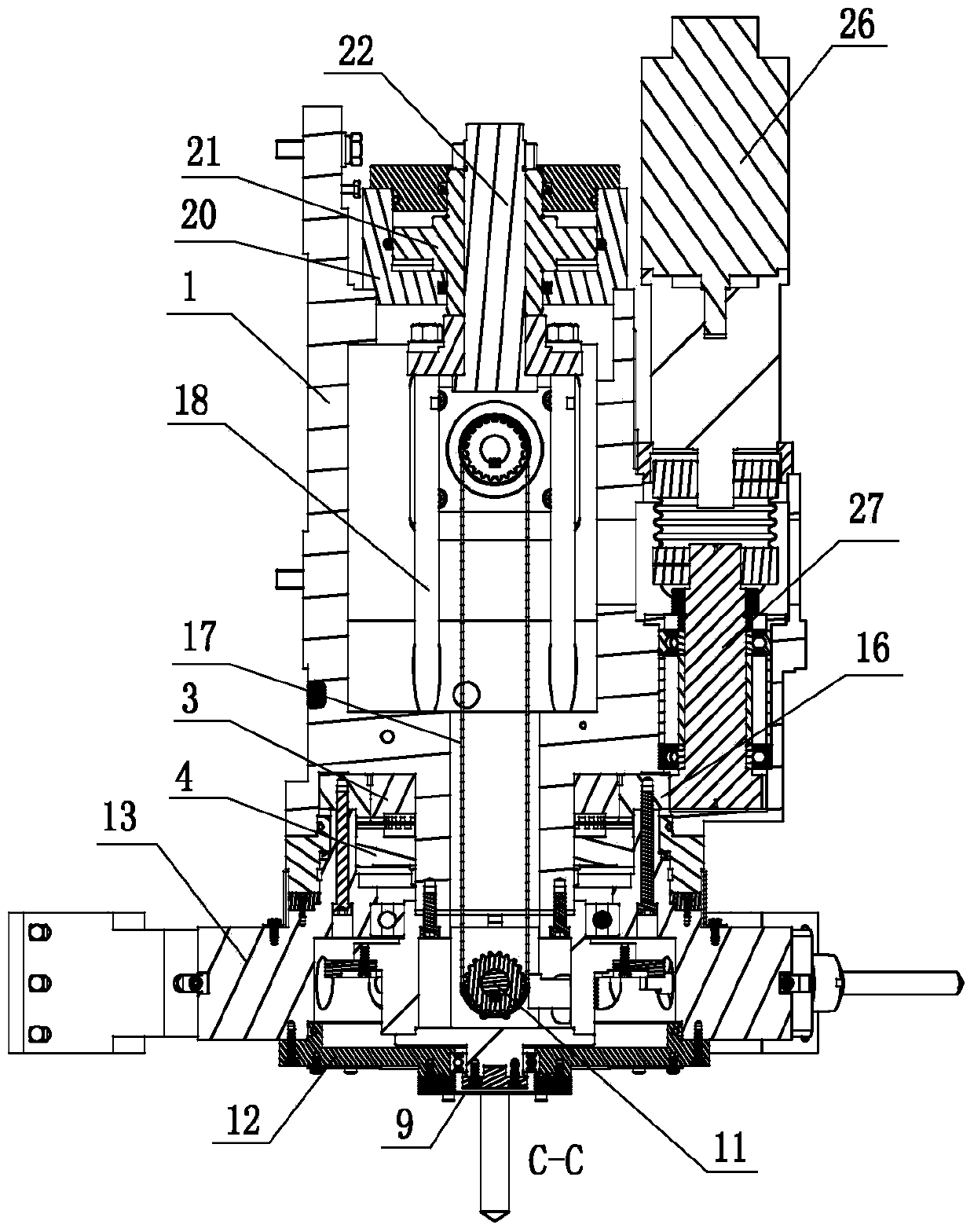
[0023] Such as Figure 1 ~ Figure 4 As shown, the present invention includes a tool holder 1 , a hollow cutter head 13 , a power drive mechanism, a tool change drive mechanism, a cutter head locking mechanism and a plurality of driven tool holders 14 . The driven knife seat 14 is installed on the cutter head 13, and a plurality of driven knife seats are distributed at intervals along the circumferential direction on the cutter head; Groove, the annular groove is peripheral to the transmission cavity, and the power drive mechanism includes a power drive motor 2, a driving shaft 19, a driven shaft 11, a hollow flange seat 6, a flange seat end cover 7 and a slave The driving shaft angle sensing mechanism, the flange seat 6 includes a hollow flange and a bearing seat sleeve 10 installed on the flange, a driven shaft hole is arranged in the bearin...


PUM


Abstract

The invention discloses a combined machining hydraulic locking power tool table, and belongs to machine tool parts. A plurality of power tool bases are arranged on a tool disc at intervals in the circumferential direction, the tool disc is fixedly connected with a transposition tooth disc and is supported through a bearing, and a gear shaft is meshed with a gear on the outer peripheral face of the transposition tooth disc for transmitting power of a tool changing drive motor. A lock oil cylinder piston is connected with a locking tooth disc through a connection piece to drive a tooth groove in the rear end face of the locking tooth disc to be correspondingly meshed with a tooth groove in the front end face of the transposition tooth disc and a tooth groove in the front end face of a fixing tooth disc fixed to a tool table base so as to achieve locking. A power drive motor transmits the rotating power to the power tool base through a drive shaft and a driven shaft which are connected in a transmission mode, the driven shaft and the power tool base are matched through a clamping groove and a clamping tenon, a driven shaft angle sensing mechanism feeds back signals to control the rotating angle of the driven shaft, the driven shaft is arranged in a radial driven shaft hole in a flange base through a bearing in a supported mode, and the tool table base is provided with a front transmission cavity and a rear transmission cavity which are used for passing of a transmission mechanism. The combined machining hydraulic locking power tool table is simple in structure and solves the problem that a traditional power tool table is complex in structure.

Description

technical field [0001] The invention belongs to a machine tool component device, and in particular relates to a hydraulic locking power tool table used in a turning-milling compound machining center. Background technique [0002] The working form of a general CNC lathe is mainly to let the spindle chuck of the lathe clamp and fix a workpiece and rotate it at high speed, use a set of tool rest devices to install various tools, and make the tool feed to perform various turning actions on the workpiece . At present, the working form of CNC lathes has been diversified, and the tool table device is also developing towards the direction of the power tool table with the function of turning and milling combined cutting, which can further achieve the function of drilling and milling processing for the workpiece, but the existing power tool table on the market Ubiquitous disadvantages such as complex structure and high cost. Contents of the invention [0003] The object of the pre...

Claims


Application Information

Patent Timeline
Patent Type & Authority Applications(China)
IPC IPC(8): B23B29/32B23Q3/155
CPCB23B29/323B23Q3/15553B23Q2003/15586
Inventor 聂志亭周德润裘圣任正法
Owner ZHEJIANG RIFA PRECISION MACHINERY
Why Eureka
Try Eureka