Eureka AIR delivers breakthrough ideas for toughest innovation challenges, trusted by R&D personnel around the world.

Connector for electrical equipment and electronic equipment and its assembling method

A technology of electronic equipment and connectors, which is applied to the parts, connections, and fixed connections of connection devices, and can solve the problems of limiting the distance between press-fit terminals 3 and shrinking

Inactive Publication Date: 2005-12-28
SUMITOMO WIRING SYST LTD
View PDF1 Cites 11 Cited by
  • Summary
  • Abstract
  • Description
  • Claims
  • Application Information

AI Technical Summary

Problems solved by technology

Thus, there arises a problem of restricting the reduction of the space between the press-fit terminals 3

Method used


Image

  • Connector for electrical equipment and electronic equipment and its assembling method
  • Connector for electrical equipment and electronic equipment and its assembling method
  • Connector for electrical equipment and electronic equipment and its assembling method

Examples


Embodiment Construction

[0045] In the following, see Figure 1-10A preferred embodiment of the present invention is described.

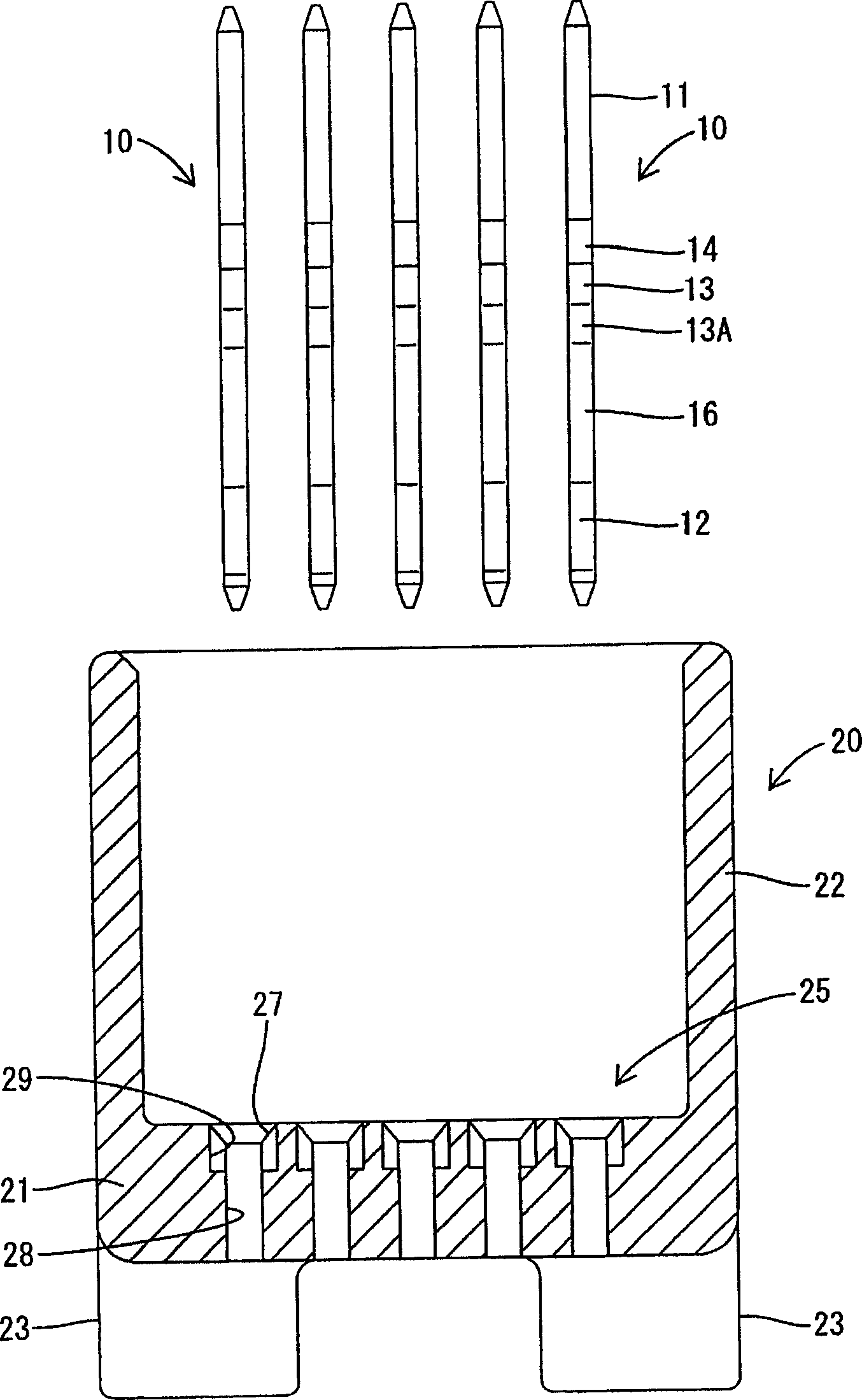
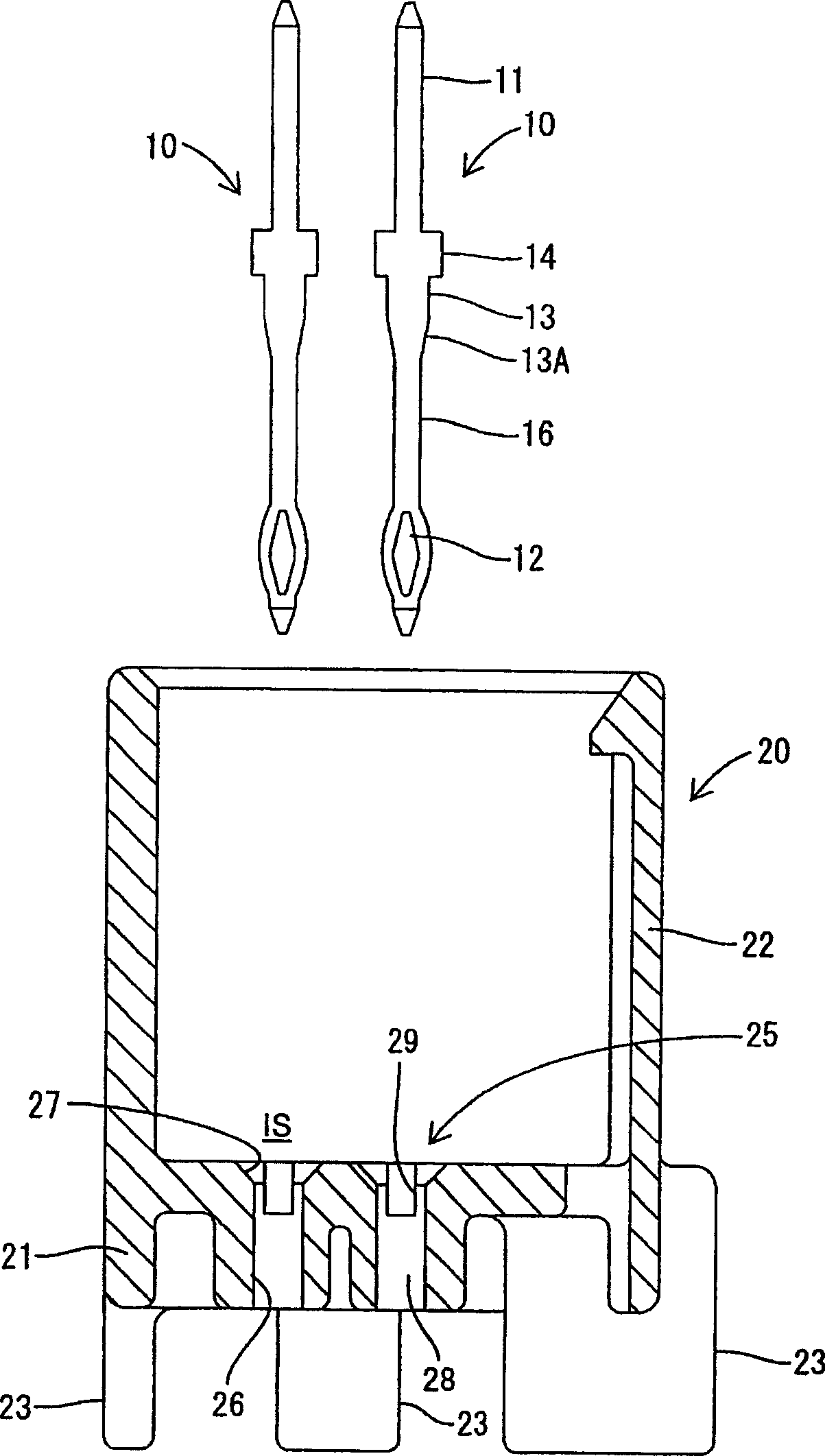
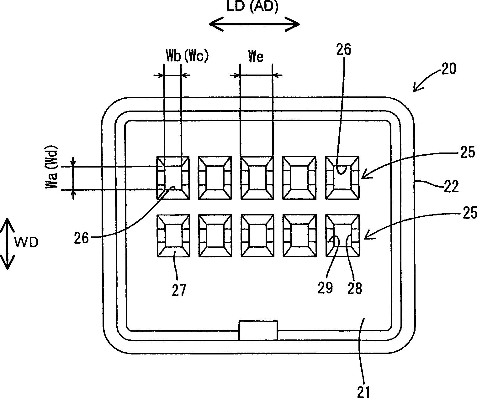
[0046] The circuit board connector of the present embodiment (as a preferred connector for connection with electrical and / or electronic equipment) is constructed in such a way that one or more, for example 10, press-fit terminals 10 are at least partially inserted, preferably Press in or assemble into as figure 1 with figure 2 The connector housing 20 (hereinafter referred to as "housing 20") is shown, and the connector will be mounted on a printed circuit board 30 (as a preferred electrical and / or electronic device, see Figure 9 , and hereinafter referred to as "circuit board 30").

[0047] Each press-fit terminal 10 is preferably formed into a shape as shown in FIGS. 5(A)-5(C) by punching or press-working a conductive (preferably metal) plate having excellent conductivity. As a whole, the press-fit terminal 20 is substantially in the form of a narrow and long recta...


PUM


Abstract

An object of the present invention is to reduce the interval between press-fit terminals while ensuring sufficient press-fit terminal holding force. Five insertion portions (25) are formed on each of the front and rear rows in the base wall (21) of the housing (20). Each insertion part (25) is formed with a relatively wide through hole (26) to allow the elastic protrusion part (12) of the press-fit terminal (10) to pass through, and a press-fit part (13) for press-fitting is also formed. ) relatively narrow press-in hole (28), wherein the width direction of the through hole (26) is consistent with the direction perpendicular to the arrangement direction of the terminals (10), and the width direction of the press-in hole (28) is consistent with the terminal ( 10) are arranged in the same direction. The elastic protrusion (12) of the press-fit terminal (10) first passes through the through hole (26) and then rotates 90° around its longitudinal axis. After that, the press-in portion (130) is pressed into the press-in hole (28), and the press-in is stopped when a stopper (14) comes into contact with the bottom surface of a receiving hole (29).

Description

technical field [0001] The present invention relates to a connector for connection to electric and / or electronic equipment, such as a circuit board connector using press-fit terminals, and to a method of assembling the same. Background technique [0002] Such as Figure 11 The circuit board connector shown is a known connector of this type. For example, a receptacle 2 that can be inserted into a mating connector is formed on the upper surface of the connector housing 1, and a plurality of press-fit terminals 3 pass through the bottom wall 2A of this receptacle 2, wherein each press-fit terminal 3 is formed There is an elastic protruding part 4 and a press-in part 6 with a stopper 5 and located above the protruding part 4 . The upper end of each press-fit terminal 3 protrudes into the socket 2, while the elastic protrusion 4 protrudes downward from the bottom wall 2A so as to be inserted into a corresponding through hole of a printed circuit board to be connected. [0003] ...

Claims


Application Information

Patent Timeline
Patent Type & Authority Applications(China)
IPC IPC(8): H01R12/51H01R12/58H01R13/41
CPCH01R12/585H01R13/41H01R13/639
Inventor 中村圭一
Owner SUMITOMO WIRING SYST LTD
Why Eureka
Eureka Blog
Learn More