Optimum lifter for slide cushion plate-transport device

A lifting device and lifter technology, which is applied in the direction of lifting devices, lifting frames, conveyor objects, etc.

Inactive Publication Date: 2004-02-11
SIEMENS AG
View PDF1 Cites 13 Cited by
  • Summary
  • Abstract
  • Description
  • Claims
  • Application Information

AI Technical Summary

Problems solved by technology

[0005] The technical problem to be solved by the present invention is to provide a lifting device that can quickly lift and lower particularly heavy loads without complicated structures

Method used


Image

  • Optimum lifter for slide cushion plate-transport device
  • Optimum lifter for slide cushion plate-transport device
  • Optimum lifter for slide cushion plate-transport device

Examples


Embodiment Construction

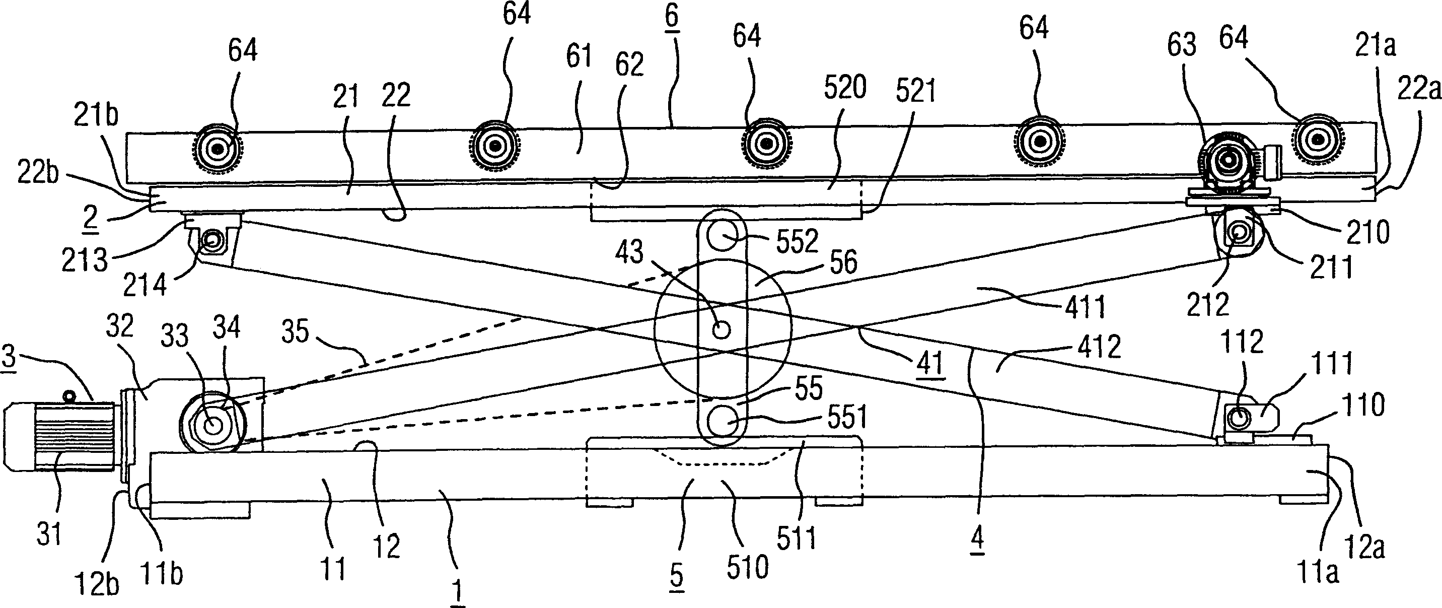
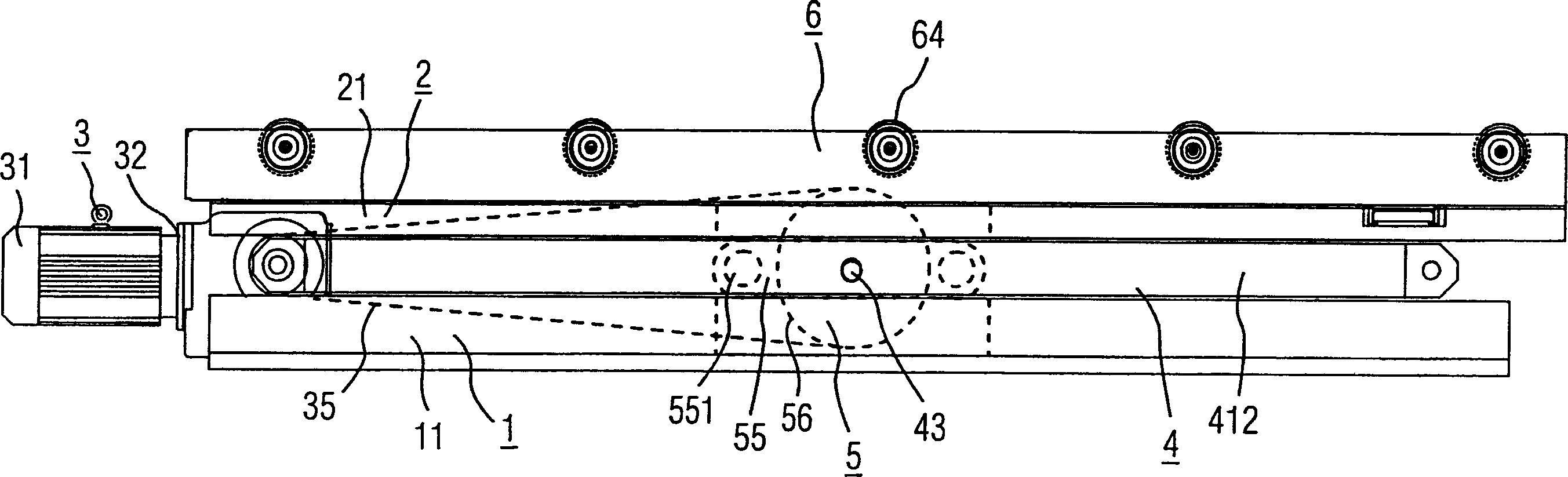
[0018] figure 1 A particularly advantageous embodiment of the lifting device according to the invention is shown as an example in a side view, in which the lifting device has been raised to the top dead center, ie to the structurally permitted maximum lifting height.

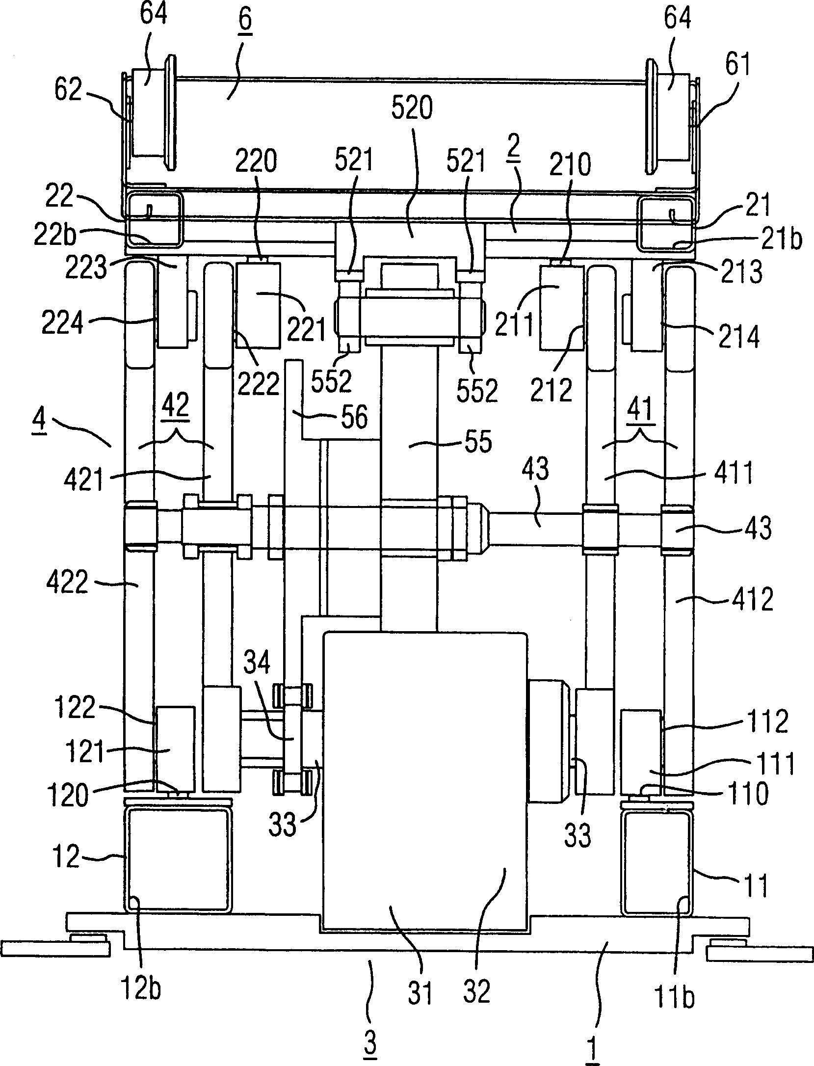
[0019] figure 1 The bottom frame of the shown design has a first and a second stringer 11 , 12 , wherein the stringer 11 lies in the plane of the drawing and the stringer 12 is behind the plane of the drawing. These longitudinal beams are firmly connected to each other by corresponding cross braces.

[0020] Between the rear end side 11b of the first longitudinal beam 11 and the rear end side 12b of the second longitudinal beam 12, a driving part 3 is mounted on the bottom frame. It preferably comprises a drive motor 31 followed by variable speed transmission 32 . On the central drive shaft 33 of the transmission 32 , which extends transversely to the longitudinal beams 11 , 12 , is mounted on the one hand a ...


PUM


Abstract

The lifting/lowering assembly, for skid conveyors, has a ground frame (1) and a carrier frame (2) which can be elevated and depressed. A scissors system (4) is between the frames, with a center axis (43), to give a parallel movement action on the carrier frame. An eccentric lifting unit (5) with an eccentric lever (55) is at the center axis, to give the raising/lowering movements by rotation around the center axis, with running rollers (551,552) riding on running rails (510,520) at both frames. The eccentric lever has a chain drive (3). The carrier frame has a roller path, for the skid movements.

Description

technical field [0001] The invention relates to a lifting device, which comprises a bottom frame and a liftable support frame, on which a load can be parked. A scissor device is used to move the supporting frame horizontally relative to the bottom frame during the lifting movement, the scissor device is supported on the bottom frame, has a central scissor axis and acts on the supporting frame in a parallel guiding manner . Background technique [0002] A device of the above-mentioned type is known from DE 1082023. In this document a lift table with so-called "Nuremberg scissors" is described. One or two independent drive levers are used to drive the scissors shaft supporting the table. The drive lever is designed in the form of a tangential cam and acts on pressure rollers which are mounted in the lower region of the legs of the scissors member. At the bottom point of the drive lever tangential to the cam is mounted a sprocket through which a chain is guided. One end of...

Claims


Application Information

Patent Timeline
Patent Type & Authority Applications(China)
IPC IPC(8): B66F7/06
CPCB66F7/065
Inventor 亚历山大·德索詹斯·克诺夫哈特穆特·马丁霍斯特·齐尔曼
Owner SIEMENS AG
Why Eureka
Try Eureka