Thermoelectric controlled x-ray detector array

A detector array and detector technology, applied in the field of X-ray detector arrays, can solve the problem that the detector array cannot maintain the operating temperature, etc.

Inactive Publication Date: 2004-02-18
GE MEDICAL SYST GLOBAL TECH CO LLC
View PDF2 Cites 27 Cited by
  • Summary
  • Abstract
  • Description
  • Claims
  • Application Information

AI Technical Summary

Problems solved by technology

Under these conditions, the heating controller cannot maintain the detector array within an acceptable operating temperature

Method used


Image

  • Thermoelectric controlled x-ray detector array
  • Thermoelectric controlled x-ray detector array
  • Thermoelectric controlled x-ray detector array

Examples


Embodiment Construction

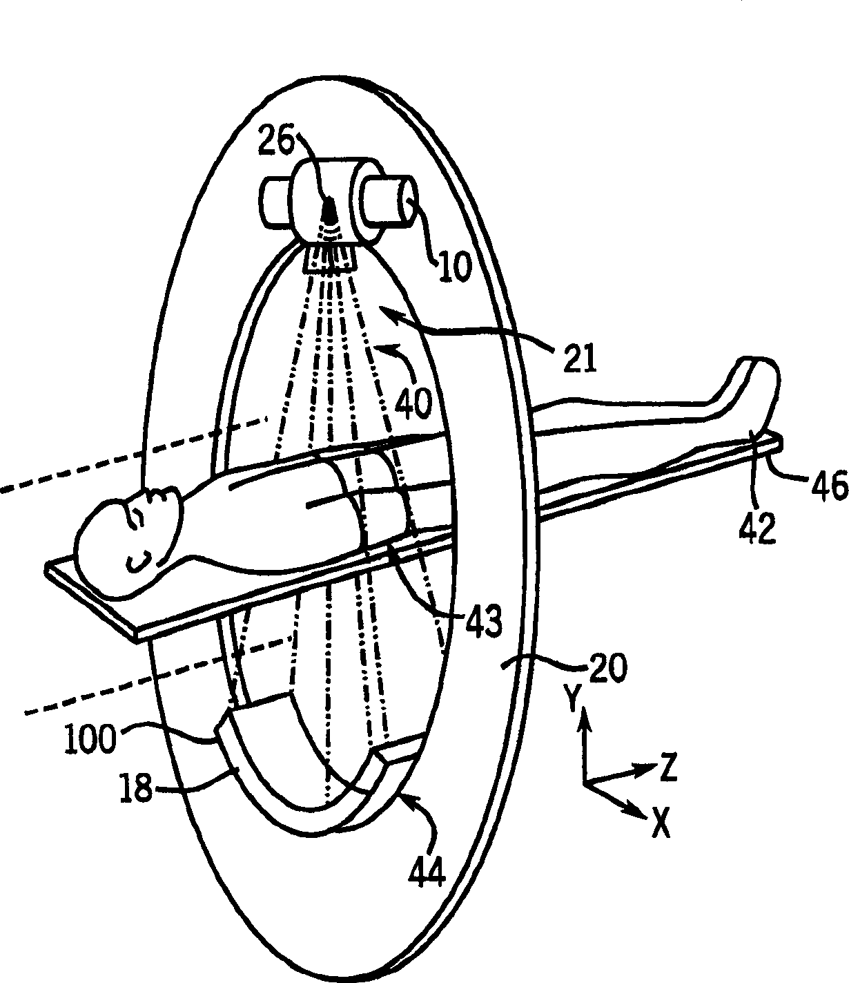
[0025] Referring now to the attached drawings and in particular figure 1 , shows a typical CT scanner used in the present invention. A CT scanner typically includes an annular gantry 20 defining a central aperture or imaging field 21 . X-ray source 10 is mounted opposite detector assembly 44 on the opposite side of imaging region 21 . The X-ray source 10 provides a fan beam 40 of X-rays directed at a portion 43 of a patient 42 resting on a support platform 46 to be scanned, and a detector assembly 44 receives the X-rays and provides the X-rays passing through the fan beam 40. The attenuation of the object corresponds to the intensity of the signal. This data is used in image reconstruction to reproduce one or more images of the object.

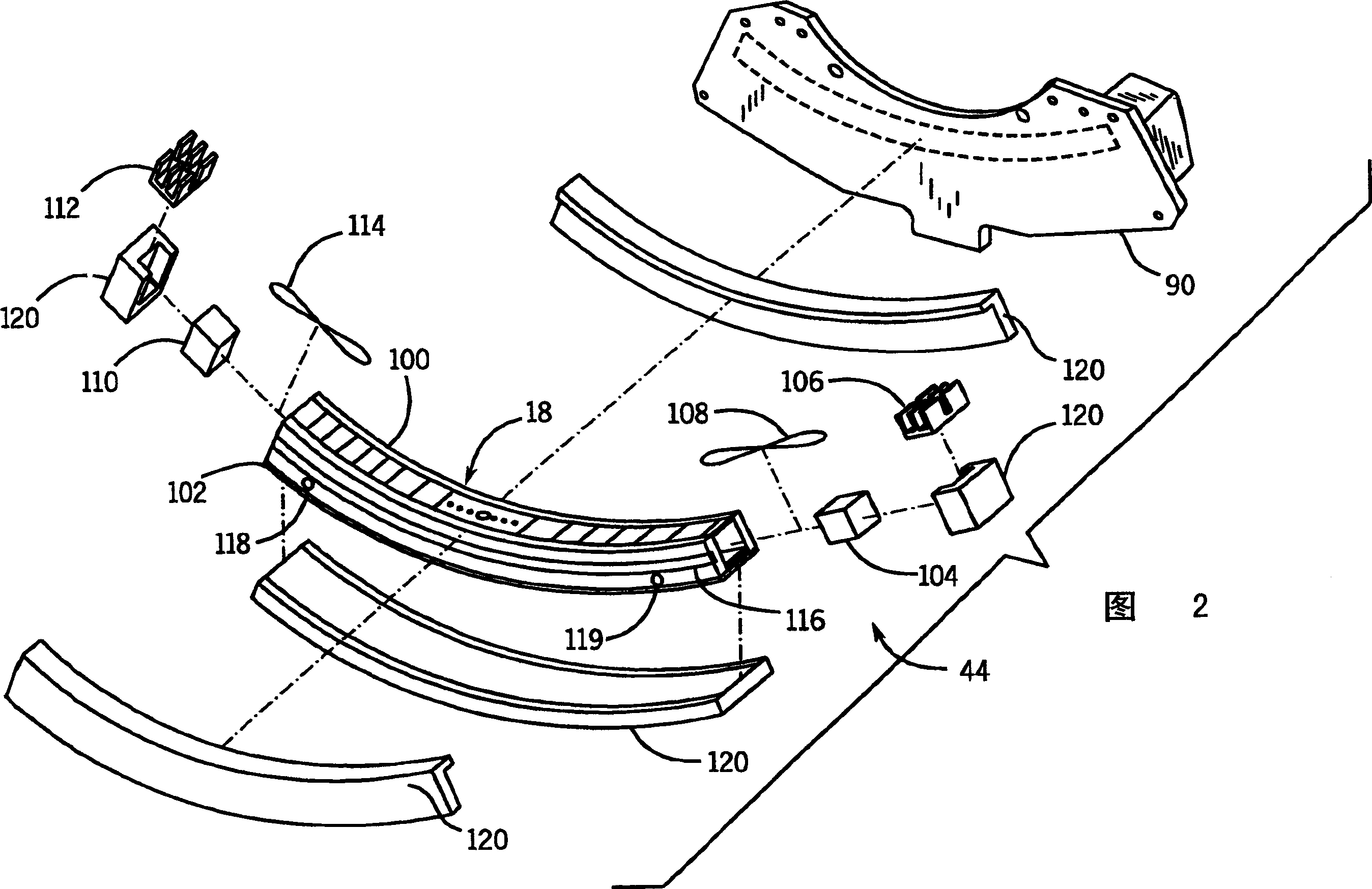
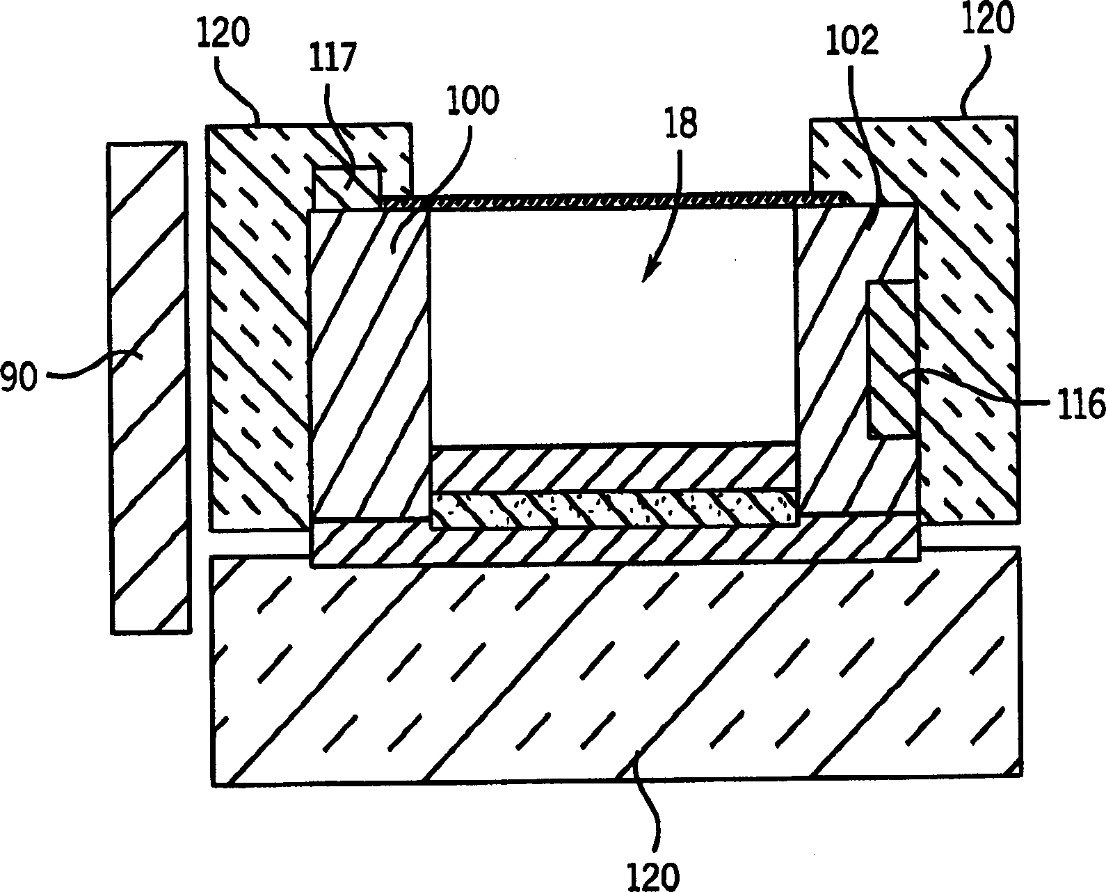
[0026] now refer to figure 1 , 2 and 3, the detector assembly 44 is connected to the rack 20 in turn (see figure 1 ) on the mounting plate 90. The detector assembly 44 includes an array of detector units 18 connected between first and se...


PUM


Abstract

Disclosed is an X-ray detector assembly for use in a computed tomography system. The X-ray detector assembly comprises an array of detector cells coupled between two rails. A thermoelectric cooler is coupled to an end of each of the rails, and is controlled to alternatively heat or cool the detector array to maintain the array in a substantially isothermal and thermally stable condition. The detector assembly preferably includes both passive and active cooling devices and insulation materials for controlling the temperature of the detector assembly. An electrical heater coupled at the center of the detector array can be used in conjunction with the TEC's to control the temperature profile of the detector array, and to minimize changes in the temperature gradients.

Description

technical field [0001] The present invention generally relates to an array of X-ray detectors for use in a computed tomography system. In particular, the invention relates to a method and apparatus for maintaining an X-ray array under substantially isothermal and thermally stable conditions. Background technique [0002] Computed tomography (CT) imaging systems typically include an x-ray source and an array of x-ray detectors mounted on opposite sides of a gantry with an imaging region interposed therebetween. The detector array typically includes a plurality of detector elements arranged in rows and columns. The detector array or module includes detection elements and associated electrical components to convert the x-ray signals into measurable analog or quantifiable digital signals. In many configurations, the array is mounted on axially separated rails of the gantry. [0003] In operation, an x-ray source generates x-rays directed at the array. When an object (such as...

Claims


Application Information

Patent Timeline
Patent Type & Authority Applications(China)
IPC IPC(8): A61B6/03G21K5/02G01T7/00
CPCA61B6/4488A61B6/035
Inventor J·J·拉西L·F·维克拉茨D·J·斯奈德
Owner GE MEDICAL SYST GLOBAL TECH CO LLC
Why Eureka
Try Eureka