
Fuel battery hydrogen saving and positive pole drain method

A fuel cell and anode technology, applied in fuel cells, fuel cell additives, circuits, etc., can solve problems such as affecting the efficiency of the cell stack, and achieve the effect of solving the hidden dangers of fire and explosion, work safety and efficiency improvement.

Inactive Publication Date: 2004-02-18
TSINGHUA UNIV
View PDF0 Cites 9 Cited by
  • Summary
  • Abstract
  • Description
  • Claims
  • Application Information

AI Technical Summary

Problems solved by technology

Frequent degassing means the loss of hydrogen fuel. The hydrogen utilization rate of the battery stack is the highest when the power is high, generally about 95%, and the hydrogen utilization rate is lower when the power is low. The

Method used


Image

  • Fuel battery hydrogen saving and positive pole drain method
  • Fuel battery hydrogen saving and positive pole drain method

Examples


Embodiment Construction

[0007] Embodiments are described below in conjunction with the accompanying drawings.

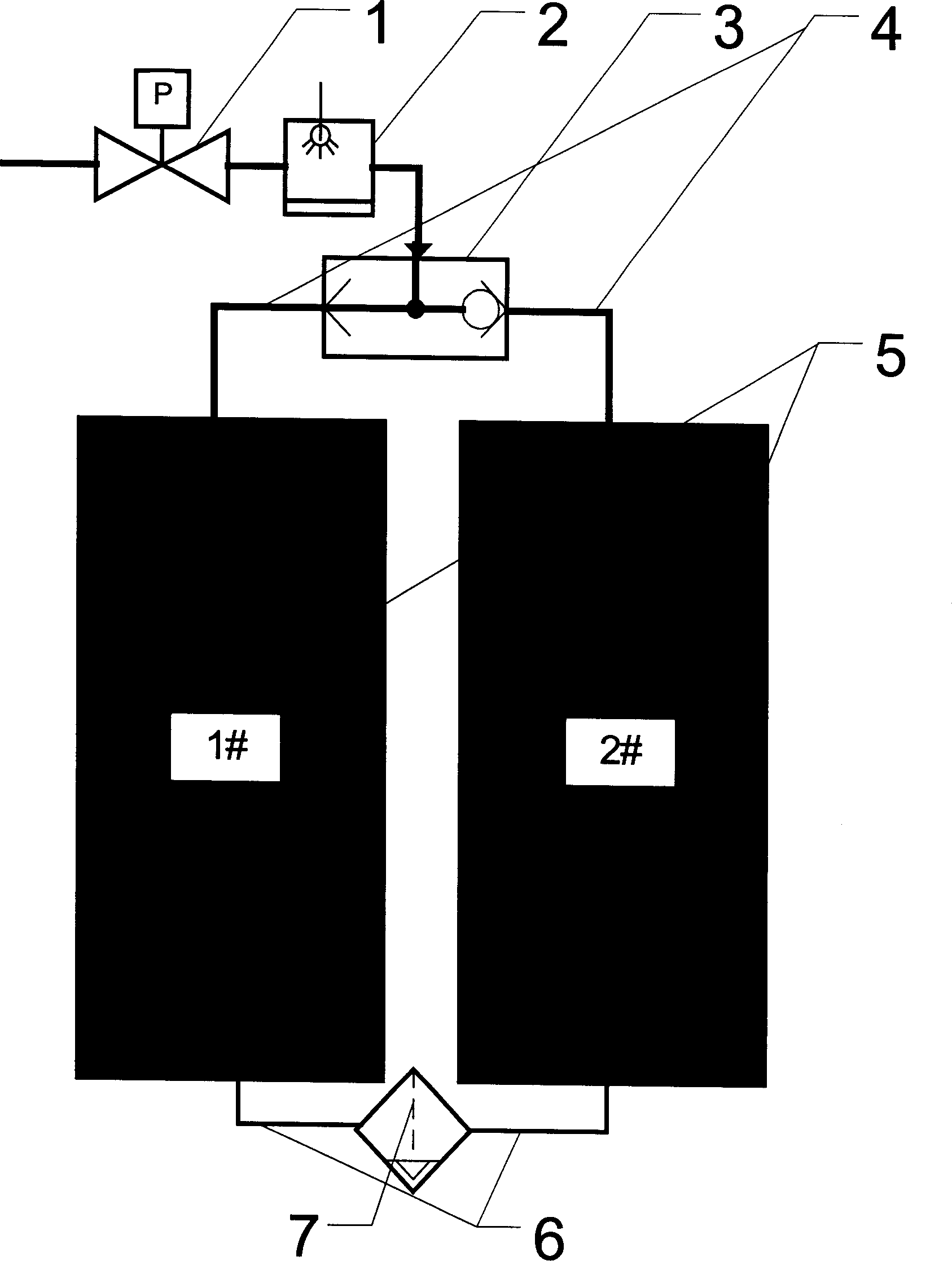
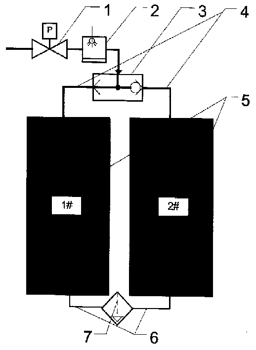
[0008] Two fuel cell stacks (1# and 2#) form a battery pair 5, and the hydrogen system consists of a hydrogen pressure regulating valve 1, a humidifier 2, a three-way valve 3, an air intake pipe 4, a connecting pipe 6 and a gas-water separator 7 . During the working process, the hydrogen flows into the 1# battery stack of the battery pair 5 through the pressure regulating valve 1, the humidifier 2, the three-way valve 3, and a branch of the intake pipe 4, and then passes through the connecting pipe 6 and the gas-water flow on the connecting pipe. The separator 7 flows into the 2# battery stack of the battery pair; after a certain time interval, the three-way valve 3 switches the channel, the branch pipe channel just ventilated on the intake pipe 4 is cut off, and the other branch pipe is opened, and the air flow first enters the 2# battery stack , and then flow into the 1# battery stack th...


PUM


Abstract

The method is to mate two piece/set fuel cell piles be an operation pair which here is called for short as of cell pair. The air inlet of each piece/set cell pile is connected with gas source throughthree-way valve at one end of the call pair and the positive pole gas pathes of two piece/set cell piles are connected by connection pipe at the other end of the cell pair as a gas-water separater isset on the connection pipe. The present invention does not need hydrogen circulation pump and frequently gas discharge, but hydrogen utilization ratio is up to 100%.

Description

technical field [0001] The invention belongs to a fuel cell hydrogen system, and relates to a method for saving hydrogen fuel and anode drainage of a cell stack. Background technique [0002] In order to improve the hydrogen-oxygen reaction efficiency of the fuel cell, it is necessary to strengthen the flow of hydrogen in the battery stack. At the same time, in order to effectively remove the water accumulated in the anode of the battery stack, an air flow pulse is often created in the hydrogen system. The method currently used is: install a hydrogen injector or a circulation pump in the hydrogen system to make the hydrogen system form a circular flow; connect a branch to the hydrogen circulation pipeline, and install a solenoid valve that intermittently opens and releases gas on the branch. The valve deflates the hydrogen system to cause airflow pulses, such as the hydrogen circulation system of XCELLSiS Fuel Cell Engines, which is also widely used in China. Frequent degas...

Claims


Application Information

Patent Timeline
IPC IPC(8): H01M8/04119
CPCY02E60/50
Inventor 裴普成
Owner TSINGHUA UNIV
Learn More