Engine-boiler integrated tube nest type combustion engine and device thereof for recovering three wastes
A waste heat recovery device and burner technology, which is applied in the direction of combustion chamber, combustion method, combustion type, etc., can solve the problems of low thermal efficiency of the system, complicated connection of the steam-water system, and easy burning of the cyclone, so as to achieve sufficient heat absorption, high thermal efficiency, The effect of improving combustion efficiency
- Summary
- Abstract
- Description
- Claims
- Application Information
AI Technical Summary
Problems solved by technology
Method used
Image
Examples
Embodiment 1
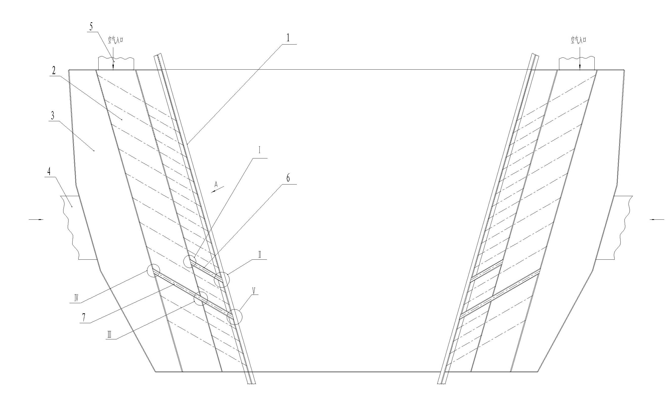
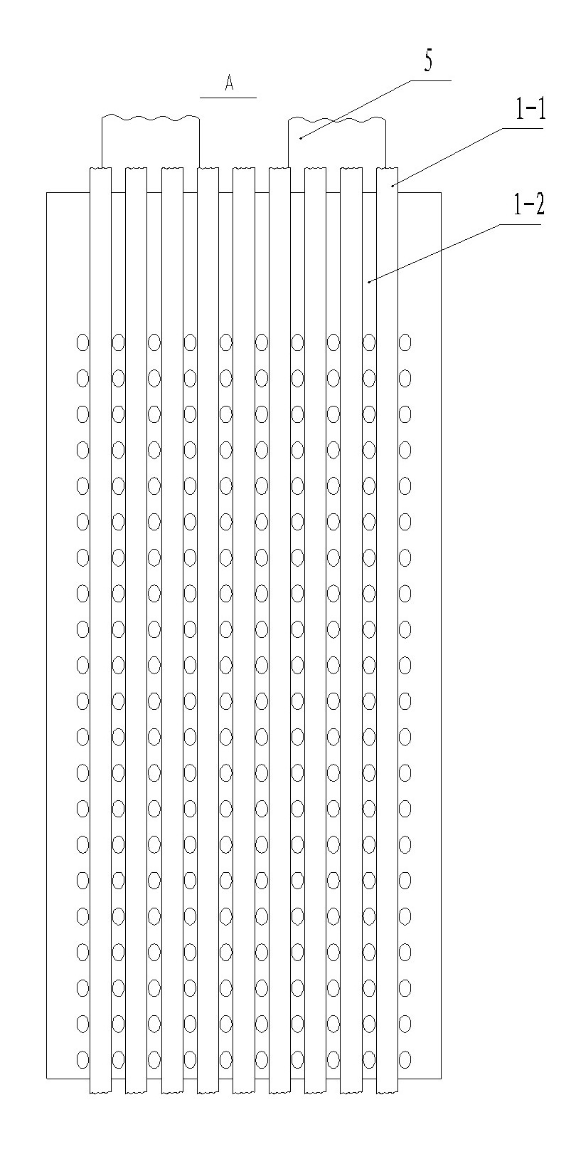
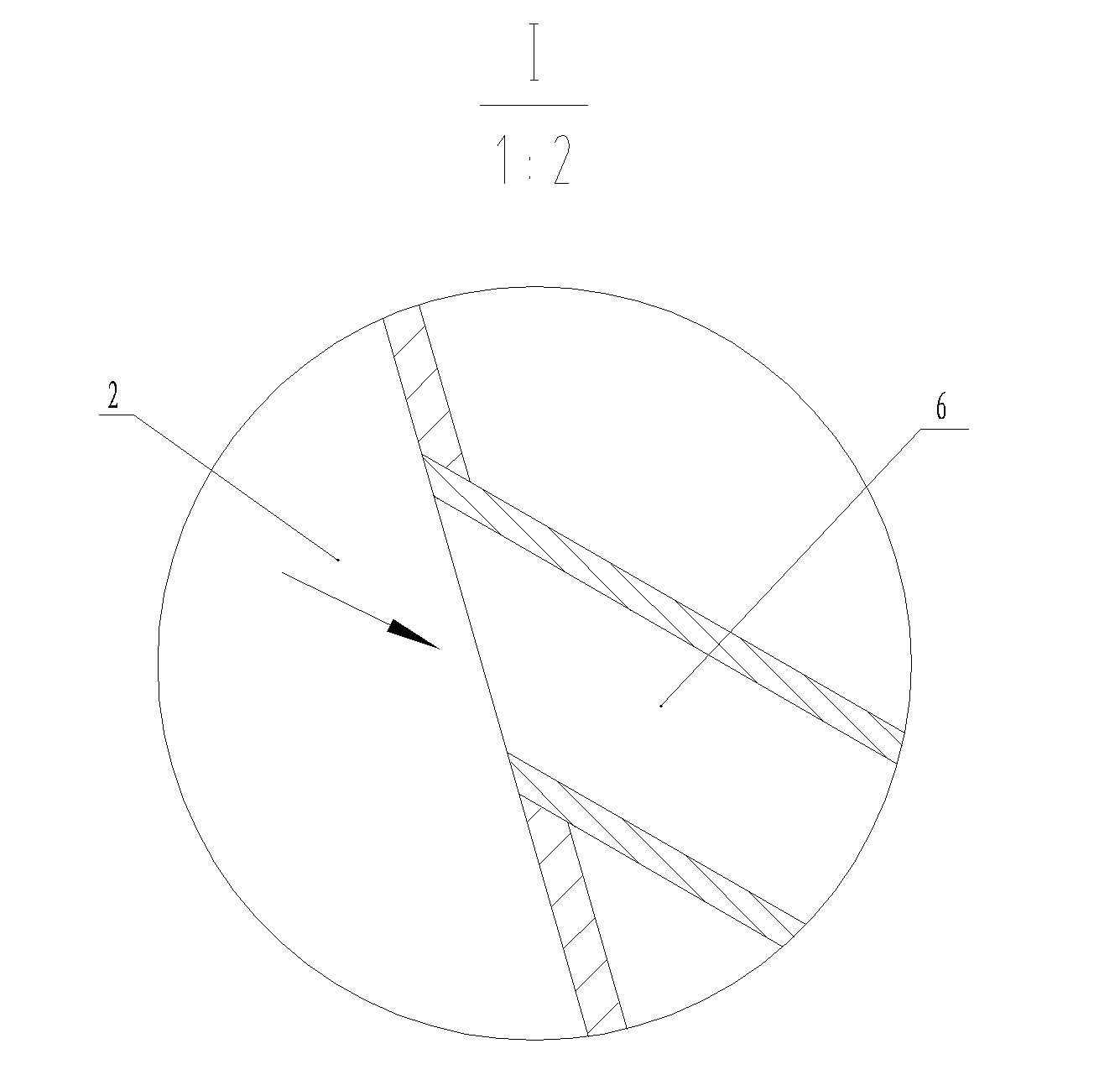
[0037] Embodiment one: see Figure 1-Figure 7 In the figure, there is a shell-and-tube burner integrated with a furnace. The burner contains a furnace with a membrane wall structure, and an air supply chamber and an air supply chamber outside the furnace. The air supply chamber is provided with an air inlet pipe. The air supply chamber is provided with a gas inlet pipe, and the inner wall of the air supply chamber is provided with a certain number of air pipes connected to the furnace with a membrane wall structure, and the inner wall of the air supply chamber is also provided with a certain number of air pipes connected To the furnace of membrane wall structure.
[0038] The membrane hearth contains heat exchange pipes and flat steel plates, and the air pipes and air pipes pass through the flat steel plates and are connected to the furnace; the air pipes and air pipes are arranged at intervals.
[0039] The air-supply chamber and the air-supply chamber are superimposed and a...
Embodiment 2
[0041] Embodiment 2: Embodiment 2 is basically the same as Embodiment 1. The accompanying drawings are not drawn, and the similarities will not be repeated. The difference is that the air supply chamber is located on the outside, and the air duct connected between the air supply chamber and the furnace runs through Pneumatic chamber.
Embodiment 3
[0042] Embodiment three: see Figure 8-Figure 11 ,as well as Figure 1-Figure 6 , a three-waste waste heat recovery device in the figure, including a co-combustion furnace, a separator, and a waste heat boiler. The lower part of the co-combustion furnace is a ignition section, the middle part is a boiling combustion section, and the upper part is a cylinder. Inlet, the air inlet of the separator is connected with the upper part of the co-combustion furnace, the gas outlet of the separator is connected with the waste heat boiler, and the dust discharge pipe of the separator is connected to the boiling combustion of the co-combustion furnace through the return device and the return pipe. section, the shell of the co-combustion furnace is a full-membrane wall structure, and the upper and lower headers are respectively arranged at the lower end and the upper end of the co-combustion furnace; the main body of the boiling combustion section of the co-combustion furnace is a machine ...
PUM
 Abstract
Description
Claims
Application Information
 - R&D
- Intellectual Property
- Life Sciences
- Materials
- Tech Scout
- Unparalleled Data Quality
- Higher Quality Content
- 60% Fewer Hallucinations
Browse by: Latest US Patents, China's latest patents, Technical Efficacy Thesaurus, Application Domain, Technology Topic, Popular Technical Reports.
© 2025 PatSnap. All rights reserved.Legal|Privacy policy|Modern Slavery Act Transparency Statement|Sitemap|About US| Contact US: help@patsnap.com


