Ignition device of natural gas engine

An ignition device and engine technology, applied in the direction of engine ignition, spark ignition controller, spark plug, etc., can solve the problems affecting the durability and ignition stability of the spark plug, unstable mixture combustion and flame propagation, low mixture gas concentration, etc. To achieve the effect of widening the concentration adaptation range, small ignition energy demand, and optimizing in-cylinder combustion

Inactive Publication Date: 2013-12-04
GUANGXI YUCHAI MASCH CO LTD
View PDF8 Cites 3 Cited by
  • Summary
  • Abstract
  • Description
  • Claims
  • Application Information

AI Technical Summary

Problems solved by technology

[0003] Traditional natural gas engines usually use an open combustion chamber, and the spark plug needs to extend into the combustion chamber to directly ignite the mixture in the combustion chamber. The disadvantage of this structure is that it is limited by the degree of leanness of the mixture in the combustion chamber. The gas mixture concentration is low, so that the ignition of the spark plug requires a considerable amount of ignition energy, that is, a higher pulse voltage is required to send a higher pulse voltage from the high-voltage wire (igniter wire) to increase the ignition energy of the spark plug, which in turn affects the durability and ignition stability of the spark plug , which also makes the combustion and flame propagation of the mixture unstable and prone to fire

Method used


Image

  • Ignition device of natural gas engine
  • Ignition device of natural gas engine
  • Ignition device of natural gas engine

Examples


Embodiment Construction

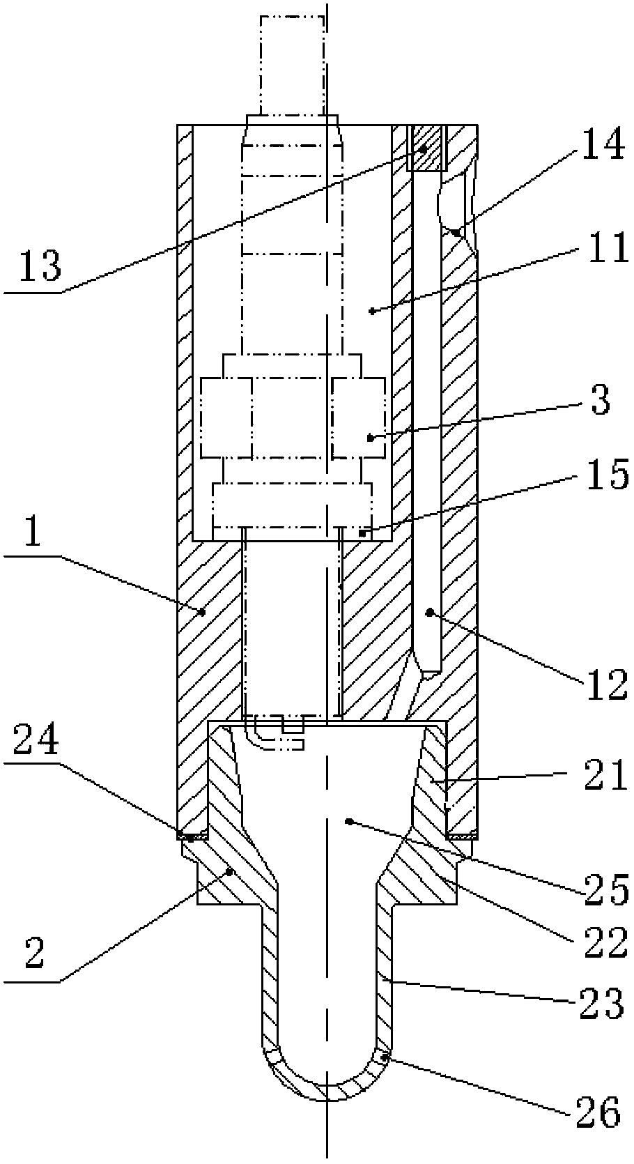
[0015] A specific embodiment of the present invention will be described in detail below in conjunction with the accompanying drawings, but it should be understood that the protection scope of the present invention is not limited by the specific embodiment. It should be understood that the "upper", "lower", "left", "right", "front" and "reverse" mentioned in the following embodiments of the present invention are all referred to figure 1 The direction shown is a reference, and these words used to limit the direction are only for convenience of description, and do not represent limitations on the specific technical solution of the present invention.

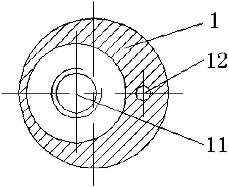
[0016] Such as figure 1 and figure 2 As shown, the natural gas engine ignition device of the present invention adopts the step combustion flame injection technology (FIS is the Flame Injection System flame injection system), namely utilizes the small ignition energy to ignite a small amount of rich mixture, generates a flame and t...


PUM


Abstract

The invention discloses an ignition device of a natural gas engine. The ignition device comprises an injection body, an injection head and a sparking plug; the injection body is cylindrical, a sparking plug installation counter bore is formed in the upper end of the injection body, and a gas channel is formed in one side of the sparking plug counter bore; an injection head installation counter bore communicated with the sparking plug installation counter bore and the gas channel is formed in the lower end of the injection body; the injection head is barrel-shaped, the upper end of the injection head is installed in the injection head installation counter bore to form a combustion space, and a flame injection hole is formed in the lower end of the injection head; the sparking plug is installed in the sparking plug installation counter bore, and an electrode at the lower end of the sparking plug stretches into the combustion space. According to the ignition device of the natural gas engine, the step-by-step combustion flame injection technology is adopted, a small quantity of rich gas mixture is ignited through a little ignition energy, a great deal of lean gas mixture is ignited after flames are produced, and therefore the successive combustion mode of the rich gas mixture in the combustion space and the lean gas mixture in a combustion chamber is achieved. The ignition device of the natural gas engine is reasonable and simple in structure, low in ignition energy requirement, and good in durability and ignition stability.

Description

technical field [0001] The invention relates to the field of engines, in particular to an ignition device for a natural gas engine. Background technique [0002] Spark plugs (spark plugs), commonly known as the burner, its function is to discharge the pulsed high-voltage electricity sent by the high-voltage wire (burner wire), break down the air between the two electrodes of the spark plug, and generate an electric spark to ignite the mixture in the cylinder. gas. The basic conditions for a high-performance engine: high-energy and stable spark, a well-mixed mixture, and a high compression ratio. [0003] Traditional natural gas engines usually use an open combustion chamber, and the spark plug needs to extend into the combustion chamber to directly ignite the mixture in the combustion chamber. The disadvantage of this structure is that it is limited by the degree of leanness of the mixture in the combustion chamber. The gas mixture concentration is low, so that the ignitio...

Claims


Application Information

Patent Timeline
Patent Type & Authority Applications(China)
IPC IPC(8): F02M57/06
Inventor 冯静沈捷覃文覃壮革
Owner GUANGXI YUCHAI MASCH CO LTD
Why Eureka
Try Eureka