Eureka AIR delivers breakthrough ideas for toughest innovation challenges, trusted by R&D personnel around the world.

Fuel injection electronic unit injector of a diesel engine

A diesel engine and fuel injection technology, applied in fuel injection pumps, fuel injection pumps, engine control, etc., can solve the problem that mechanical synthetic pumps cannot meet Euro III and above emission standards, the pressure at the pump end is difficult to increase, and the volume of high-pressure pipelines Large and other problems, to achieve the optimal fuel injection time, reduce the reset load, improve the effect of combustion in the cylinder

Active Publication Date: 2010-06-23
中曼发动机江苏有限公司
View PDF0 Cites 5 Cited by
  • Summary
  • Abstract
  • Description
  • Claims
  • Application Information

AI Technical Summary

Problems solved by technology

These two injection devices have low control accuracy, poor flexibility, and narrow control range. The road is long, there is pressure loss, the pressure of the fuel injection pump is usually lower than 1500bar, and pressure fluctuations such as residual pressure and reflected waves will cause abnormal injection; there are various straight grooves and inclined grooves on the plunger, which increase leakage and reduce strength and stiffness , the pressure at the pump end is difficult to increase above 1300bar
Due to these shortcomings, mechanical synthetic pumps cannot meet Euro III and above emission standards
The electronically controlled unit pump also limits the increase in fuel injection pressure and the reduction of emission standards

Method used


Image

  • Fuel injection electronic unit injector of a diesel engine
  • Fuel injection electronic unit injector of a diesel engine
  • Fuel injection electronic unit injector of a diesel engine

Examples


Embodiment Construction

[0024] In order to make the technical means, creative features, goals and effects achieved by the present invention easy to understand, the present invention will be further described below in conjunction with specific embodiments.

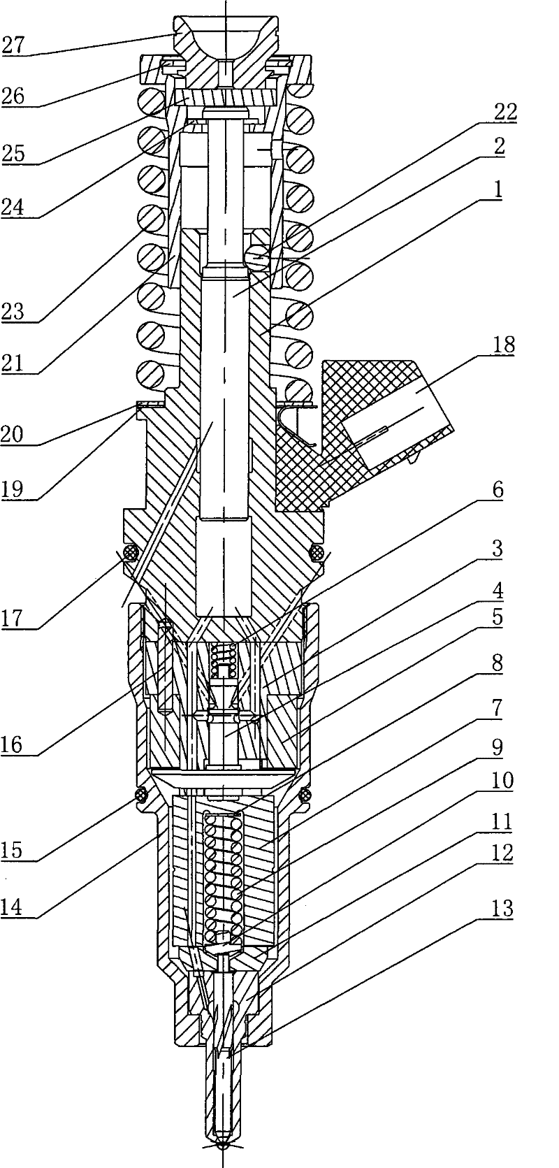
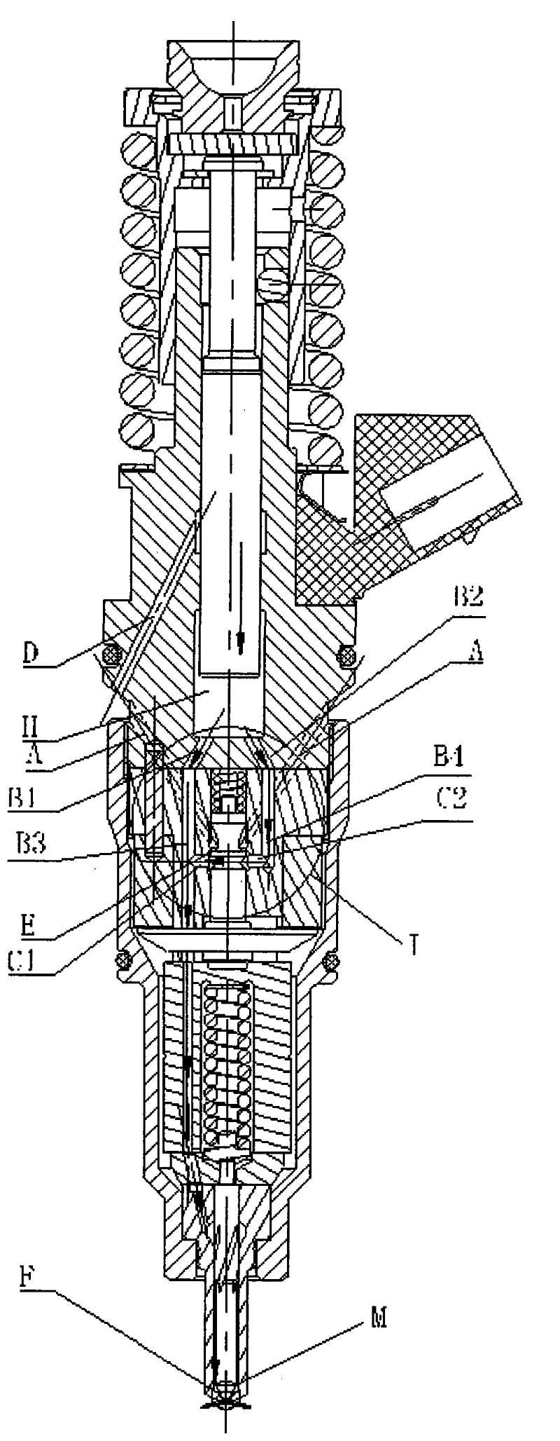
[0025] Such as figure 1 As shown, the diesel engine fuel injection electronically controlled pump nozzle of the present invention includes a pump body 1, a plunger coupler, a plunger spring 23, a plunger spring seat 7, a retaining ring 26, a rocker arm pad 27, and a plunger pad 25. Open retaining ring 24, lock ball 22, fuel injector nut 14, solenoid valve, socket 18 and fuel injector. The fuel injector and the electromagnetic valve are stacked in the fuel injector nut from bottom to top and connected with the plunger couple with threaded pretightening; the plunger spring 23, the circlip 26, the rocker pad 27 and The plunger spacer 25 is fixed on the plunger spring seat 7, and is fixed and limited by the lock ball 22 through the open retaining rin...


PUM


Abstract

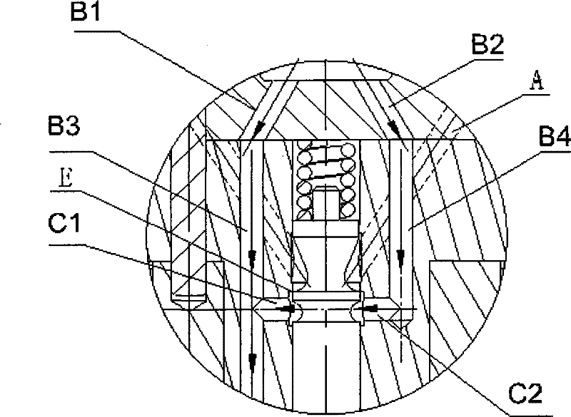
The invention discloses a fuel injection electronic unit injector of a diesel engine, which comprises a plunger and barrel assembly, a plunger spring, a plunger spring base, a plunger cushion block, an elastic collar, a rocker cushion block, a fuel atomizer nut, an electromagnetic valve and a fuel atomizer, wherein the fuel atomizer and the electromagnetic valve are stacked in the electromagnetic valve nut from bottom to top, and are tightly connected with the plunger and barrel assembly through threads in advance; a pump body and a control valve base are provided with auxiliary pressure fuel passages (including pressure fuel passages and bypass fuel passages) communicated with a fuel pressure cavity and a main pressure fuel passage leading to the fuel atomizer; and one to three fuel passages and bypass fuel passages are arranged in pairs. The invention can realize the accurate and flexible control of optimum fuel injection quantity, optimum fuel injection time and fuel injection pressure, improve combustion in the engine cylinder, increase fuel taking speed and quantity, and reduce fuel sucking resistance and friction when a spool moves and the reset load of the plunger spring so that the harmful effulent of the engine is reduced and the economical, dynamic and intelligent properties of the engine are improved.

Description

technical field [0001] The invention relates to a pump nozzle for a diesel engine, in particular to a fuel injection electronically controlled pump nozzle for a medium-power diesel engine. Background technique [0002] Existing diesel engine fuel injection devices are mechanical synthetic pumps or electronically controlled unit pumps. The mechanical synthetic pump is composed of fuel injection pressure regulating mechanism, fuel injection quantity regulating mechanism, fuel injection time regulating mechanism and injection mechanism. The fuel injector of the electronically controlled unit pump has an independent oil pump, which is simplified in structure, but still retains the high-pressure pipeline. These two types of injection devices have low control precision, poor flexibility, and narrow control range. The road is long, there is pressure loss, the pressure of the fuel injection pump is usually lower than 1500bar, and pressure fluctuations such as residual pressure and...

Claims


Application Information

Patent Timeline
IPC IPC(8): F02M61/04F02M61/06F02M57/02F02M59/02F02D1/00
Inventor 陈伯林
Owner 中曼发动机江苏有限公司
Why Eureka
Eureka Blog
Learn More