Projection display device and magnetic screen device

A technology of projection display and magnetic screen, applied in the direction of using the image reproducer of the projection device, electrode device and related parts, static indicator, etc., can solve the problem that the magnetic screen cannot produce enough effect, limit the thickness and shape of the magnetic screen, shield And other issues

Inactive Publication Date: 2004-02-18
KK TOSHIBA
View PDF1 Cites 0 Cited by
  • Summary
  • Abstract
  • Description
  • Claims
  • Application Information

AI Technical Summary

Problems solved by technology

[0007] If a magnetic screen as disclosed in the above publication is provided in a projection display apparatus, the above-mentioned misconvergence can be suppressed, but such a magnetic screen cannot produce a sufficient effect
Therefore, the effect of the devices disclosed in the above publications is not satisfactory in a practical sense
[0008] Also, the above publications do not suggest any shielding for the klystron, or suggest any method of connecting the klystron, although it is generally connected to the CRT
Moreover, the thickness and shape of the magnetic shield are limited

Method used


Image

  • Projection display device and magnetic screen device
  • Projection display device and magnetic screen device
  • Projection display device and magnetic screen device

Examples


Embodiment Construction

[0024] Embodiments of the present invention are described below in conjunction with the accompanying drawings.

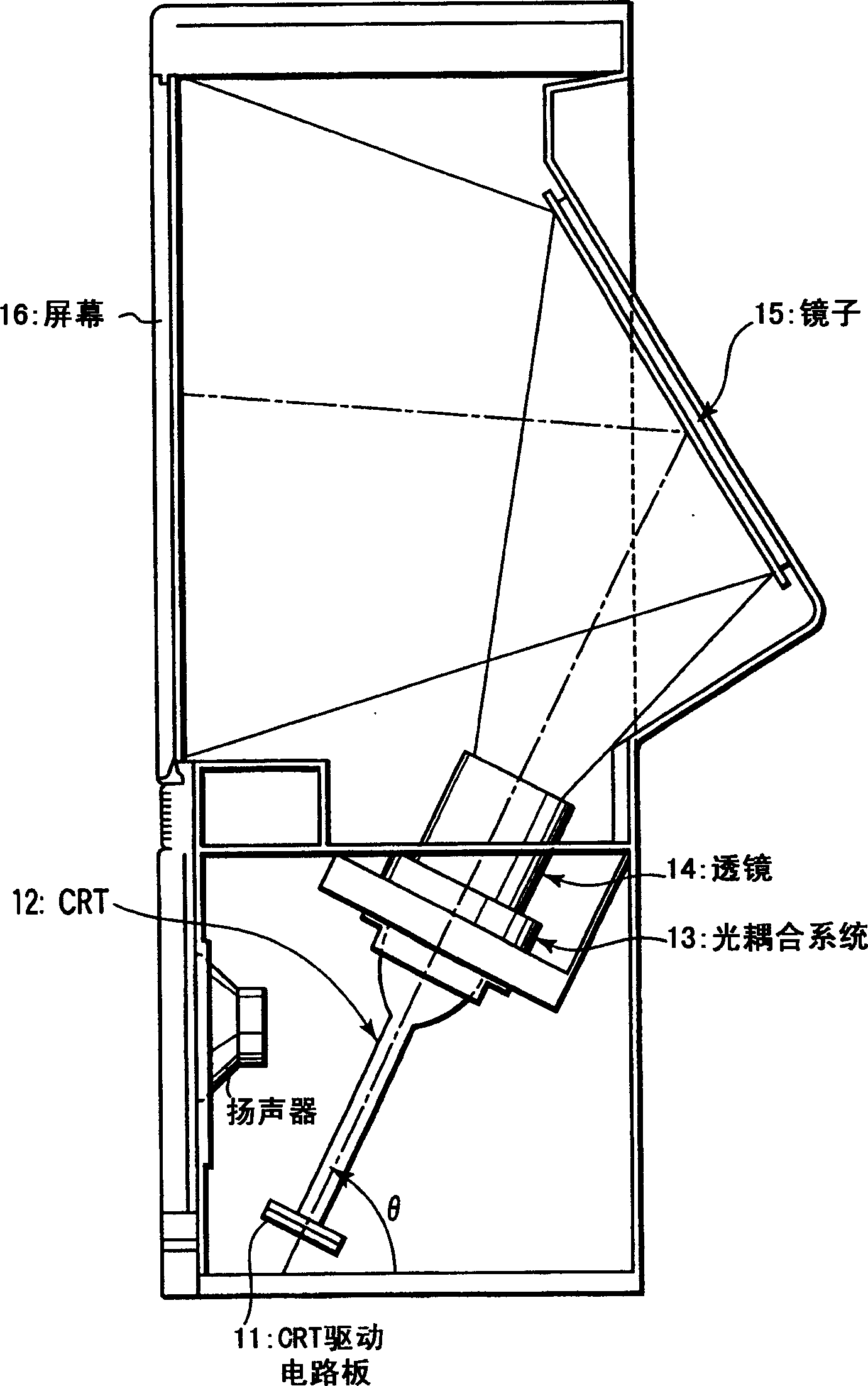
[0025] figure 1 It is a cross-sectional view showing a CRT-based projection display device according to an embodiment of the present invention. The comparison diagram schematically shows the overall structure of the optical system. In this figure, deflection yokes, klystron coils, shielding plates, etc. are omitted, which will be described later.

[0026] exist figure 1 In the above, the CRT driving circuit board 11 is connected to the CRT 12, so that the CRT 12 is driven by the video signal supplied from the driving circuit board 11. Accordingly, corresponding video images are displayed on the fluorescent screen of the CRT 12 . The video image displayed on the fluorescent screen of the CRT 12 is incident on the lens 14 through the optical coupling system 13 . The optical coupling system 13 is filled with refrigerant to absorb heat generated by the CRT 12 durin...


PUM


Abstract

In a CRT-based projection display apparatus that displays on a screen video images displayed on three CRTs for red, green, and blue respectively, by projecting the video images against a screen so that the video images are enlarged and synthesized, a deflecting yoke and a velocity modulating coil (7) are attached to a neck portion (12a) of each CRT (12). Furthermore, a cylindrical magnetic shield (3) is arranged so as to cover a coil portion (7a) of the velocity modulating coil (7) and a cathode (12b) of the CRT.

Description

technical field [0001] The present invention relates to electronic equipment using a CRT (cathode ray tube) as a display device, and more particularly, to a projection display device and a magnetic shield device. Background technique [0002] In CRTs used in television receivers and the like, electron beams emitted from electron guns are scanned in the horizontal and vertical directions by means of deflection yokes, striking the phosphor screen of each CRT. Another well-known method is to install a klystron coil near the deflection yoke to adjust the horizontal scanning speed of the electron beam in the brightness changing part of the video, so as to make the isofield lines of the video signal clear. [0003] In the case of an ordinary color CRT, an electron gun emits three kinds of electron beams, which respectively impinge on respective predetermined positions of corresponding phosphor screens with predetermined intensities. Thus, the red, green and blue light-emitting el...

Claims


Application Information

Patent Timeline
Patent Type & Authority Applications(China)
IPC IPC(8): H01J29/00G09G1/04H01J29/02H01J29/76H01J31/10H04N5/64H04N5/74H04N9/31
CPCH01J29/76H01J2229/003H01J2229/8636H01J2229/5688H01J2229/0015
Inventor 大嶋賢一
Owner KK TOSHIBA
Why Eureka
Try Eureka