Machine for cutting wafers

A technology for cutting machines and wafers, applied in the direction of routers, sawing equipment, metal sawing equipment, etc., can solve the problems of small parallel cutting, separation disc approach, low function and efficiency of wafer cutting machines, etc.

Inactive Publication Date: 2004-02-25
DISCO HI TEC EURO
View PDF0 Cites 2 Cited by
  • Summary
  • Abstract
  • Description
  • Claims
  • Application Information

AI Technical Summary

Problems solved by technology

[0006] In this way a disadvantage of the known wafer cutting machines is found, that due to the combination and structure of the working shaft and the separating discs it is not possible to perform very small parallel cuts because the separating discs cannot approach each other in a suitable way
This results in lower functionality and efficiency of the wafer dicing machine

Method used


Image

  • Machine for cutting wafers
  • Machine for cutting wafers
  • Machine for cutting wafers

Examples


Embodiment Construction

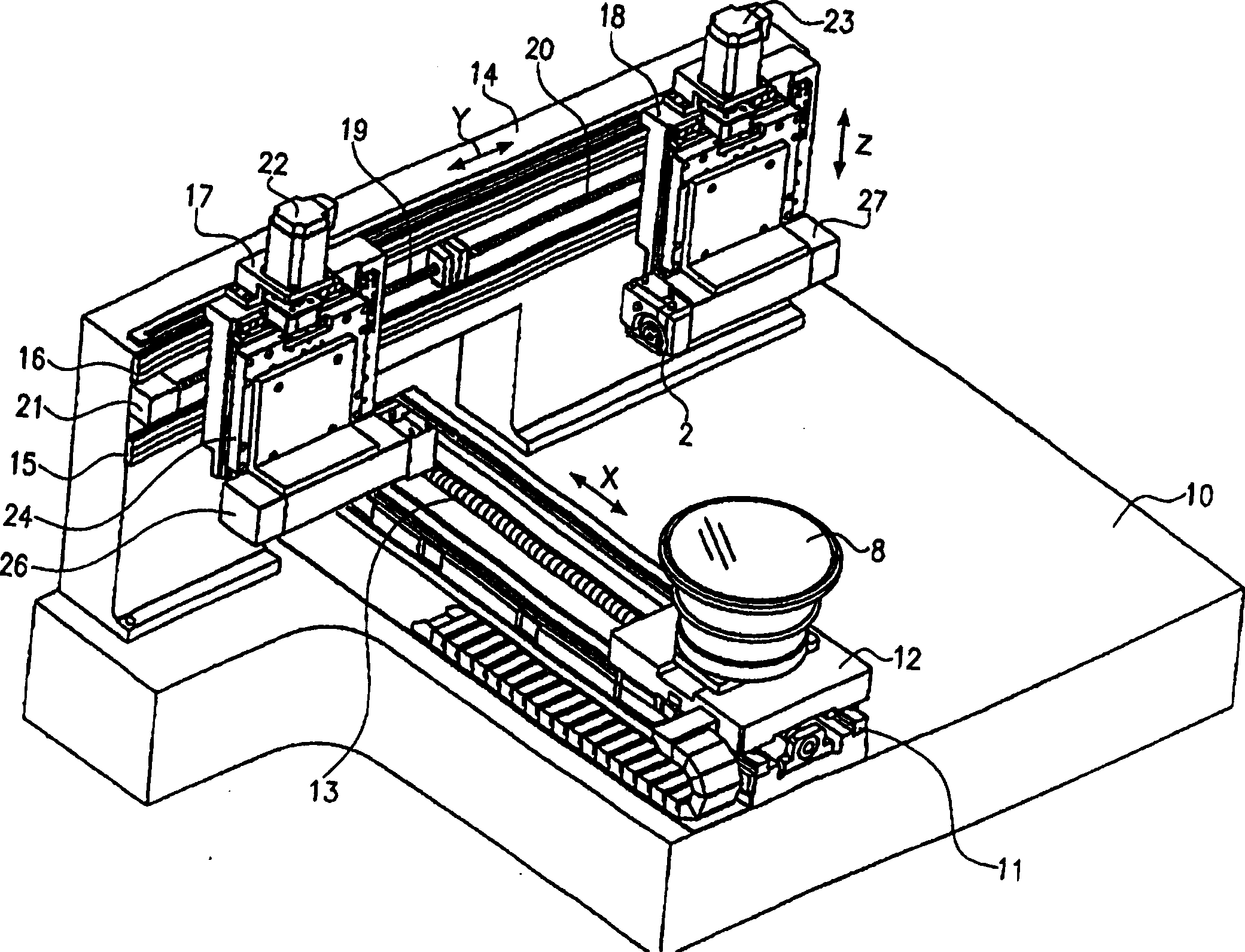
[0020] figure 1 is a perspective view of a wafer dicing machine according to the present invention. The cutting machine comprises a frame 10 fastened to a guide 11 supporting thereon a carriage 12 in a longitudinally displaceable manner on the guide 11 . The carriage 12 can be moved, for example, by means of a ball screw 13 . The carriage 12 carries a working platform 8 which is rotated around a vertical axis by a drive (not shown).

[0021] The frame 10 secures an operating table 14 comprising mutually parallel horizontal guides 15, 16 on which carriages 17, 18 are supported in a horizontally movable direction. Their movement is achieved by means of ball screws 19, 20 or similar, here moved by a drive 21 in a known manner.

[0022] The two carriages 17 and 18 each have mounted thereon a motor 22 and 23 for vertically moving the carrying carriages 24, 25 by means of a drive system (not shown).

[0023] The carrier slides 24 , 25 each have a bearing block 26 , 27 each havin...


PUM


Abstract

The invention relates to a machine (1) for cutting wafers, comprising two rotatable work spindles (1, 2) which are coaxially arranged in relation to each other. Said spindles respectively carry, on the ends thereof, a cutting-off wheel (3, 4) positioned on a hub (5, 6), and can be displaced in relation to a working table (8) on which a wafer (7) can be mounted. The inventive machine is characterised in that the two cutting-off wheels (3, 4) are arranged in such a way that they are oriented in relation to each other, the hub (5, 6) being positioned on the rear side of the cutting-off wheel (3, 4) and arranged on the working spindle (1, 2).

Description

technical field [0001] The invention relates to a wafer cutting machine. Background technique [0002] The present invention relates to a wafer dicing machine comprising two interrelated rotatable work shafts arranged coaxially, at the end of each work shaft there is a separator disc supported on a hub, and each The work axis is movable relative to a work platform suitable for disposing of a wafer. [0003] Such wafer dicing machines are known to be of a very different design than the prior art. They can be used to separate individual chips, or other electronic components, fabricated on a wafer during chip fabrication. [0004] The individual chips or chip blanks are square most of the time and the wafers are first cut into strips. Each strip has the width of the chip or chip semi-finished product to be made. After the separation disk cuts a large number of parallel thin strips from the wafer, the working platform and the wafer rotate 90 ...

Claims


Application Information

Patent Timeline
IPC IPC(8): B23D61/02B27B5/32B28D5/02
CPCB28D5/029B27B5/32B23D61/025B23D5/02
Inventor 卡尔·普力沃斯
Owner DISCO HI TEC EURO
Why Eureka
Try Eureka