Disposable syringe

A syringe and disposable technology, applied in the field of medical devices, can solve the problem of not being used for the second time and can only be discarded, and achieve the effect of preventing virus cross-infection

Inactive Publication Date: 2004-03-17
陆爱平
View PDF0 Cites 0 Cited by
  • Summary
  • Abstract
  • Description
  • Claims
  • Application Information

AI Technical Summary

Problems solved by technology

[0003] The purpose of the present invention is to overcome the shortcomings of currently used disposable syringes, an

Method used


Image

  • Disposable syringe
  • Disposable syringe
  • Disposable syringe

Examples


Example Embodiment

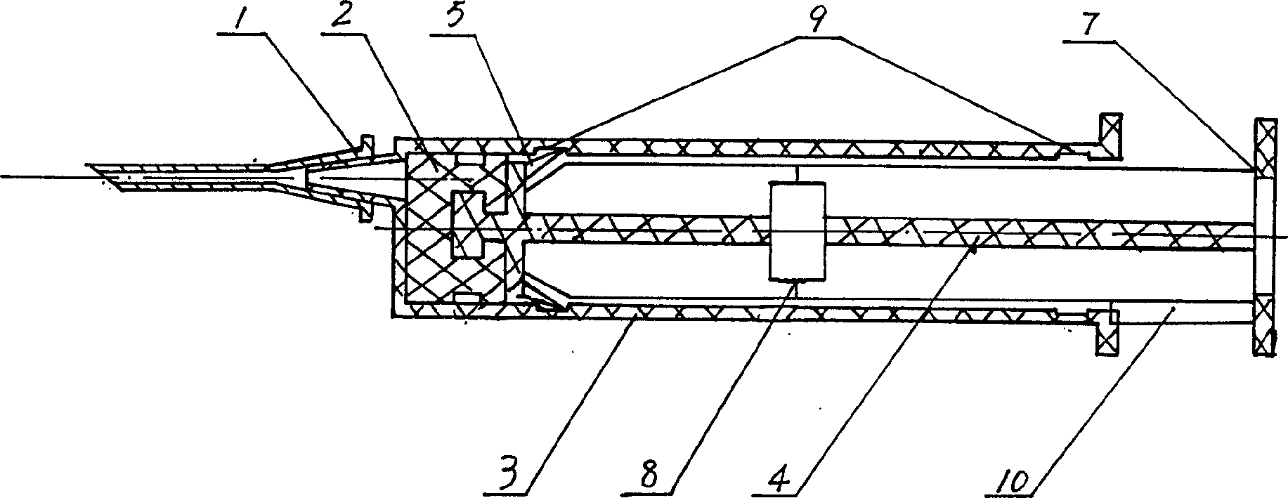
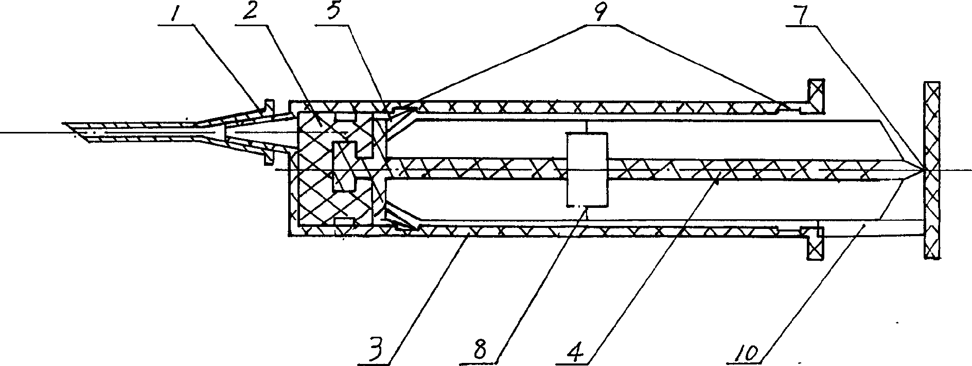
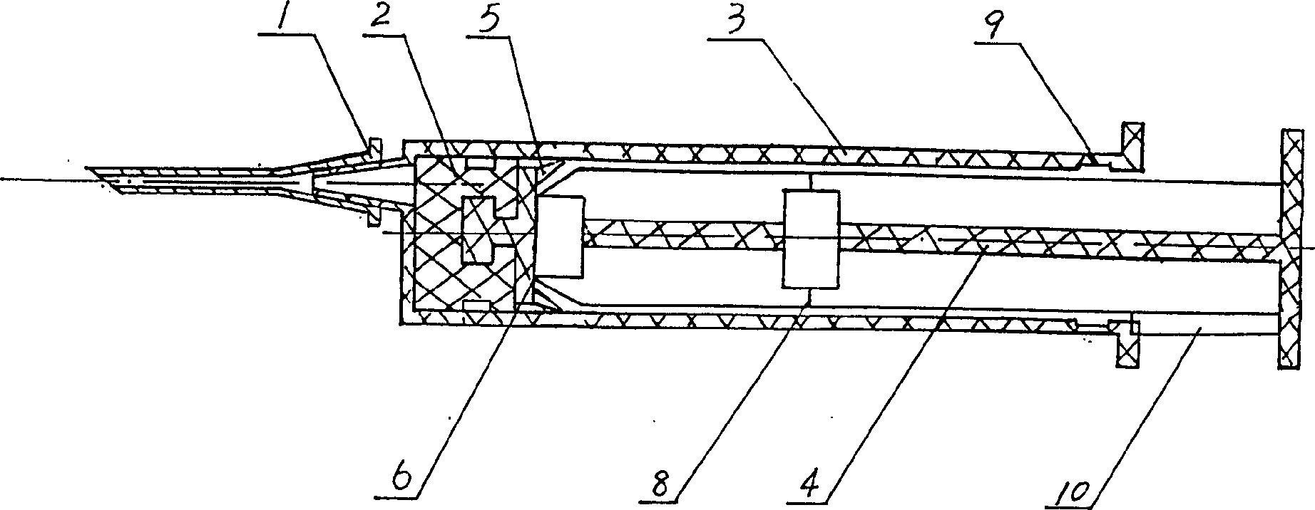
[0008] When implementing, press figure 1 , figure 2 , image 3 , Figure 4 , Figure 5 , Figure 6 And many different combinations. The following introduction figure 1 , The longitudinal section of the front half and the back half of the inner wall of the plastic needle sleeve 3 is rectangular grooves 9 arranged in the plastic injection rod 4 when the plastic injection rod 4 is pushed forward to the end, the plastic injection rod 4 5 The tooth tip just fits into the rectangular groove 9 so that the plastic injection rod 4 cannot be pulled out. If it is pushed hard, the edge connection points of the front and rear cross 8 on the plastic injection rod will be broken. If it is pulled hard, the plastic injection rod will cross the rear cross. 14 and the edge connection point of the plastic injection rod handle 7 is broken. Therefore, it cannot be used twice. The longitudinal section of the rear half of the inner wall of the plastic needle sleeve 3 is a rectangular groove 9, which i...


PUM


Abstract

The disposable syringe for intravenous injection and intramuscular injection consists of plastic tube, rubber piston, plastic injection rod and needle. The rubber piston is in the front of the injection rod and the plastic injection rod is inside the plastic tube. The plastic injection rod has several fragile parts, several elastic backwards sawtoothed fins and one limiting part, and the plastic tube has longitudinal rectangular grooves on the inner wall. Once the syringe is used, the elastic fins will be jammed in the grooves and the injection rod is hard to withdraw. Further pushing or pulling the injection rod will damage the injection rod and this can avoid the repeated use of the syringe and thus caused cross infection.

Description

Technical field: [0001] The invention relates to a medical device, in particular to a disposable syringe for intravenous injection or intramuscular injection. Background technique: [0002] Currently used disposable syringes, although the name is disposable syringes, all have the possibility of being used again or multiple times, and its weak point is that it cannot prevent the occurrence of cross-infection. Invention content: [0003] The purpose of the present invention is to overcome the disadvantages of currently used disposable syringes, and provide a disposable syringe that can only be discarded after one injection and cannot be used for the second time. [0004] The purpose of the present invention is achieved through the following technical solutions. The disposable syringe consists of a plastic needle cover, a rubber piston, a plastic injection rod, a limit rod and an injection needle. The rubber piston is arranged on the front end of the plastic injection rod, ...

Claims


Application Information

Patent Timeline
IPC IPC(8): A61M5/31A61M5/50
Inventor 陆爱平
Owner 陆爱平
Why Eureka
Try Eureka