Honing method and honing equipment

A technology of honing and equipment, which is applied in the direction of honing machine tools, metal processing equipment, manufacturing tools, etc., can solve the problems of prolonging machining time and increasing manufacturing costs, and achieve the effects of avoiding machining time, reducing plastic flow, and avoiding prolongation

Inactive Publication Date: 2004-04-07
NISSAN MOTOR CO LTD
View PDF1 Cites 7 Cited by
  • Summary
  • Abstract
  • Description
  • Claims
  • Application Information

AI Technical Summary

Problems solved by technology

However, these measures disadvantageously prolong the machining time and increase the manufacturing cost

Method used


Image

  • Honing method and honing equipment
  • Honing method and honing equipment
  • Honing method and honing equipment

Examples


Embodiment Construction

[0029] Hereinafter, embodiments of the present invention will be described with reference to the accompanying drawings.

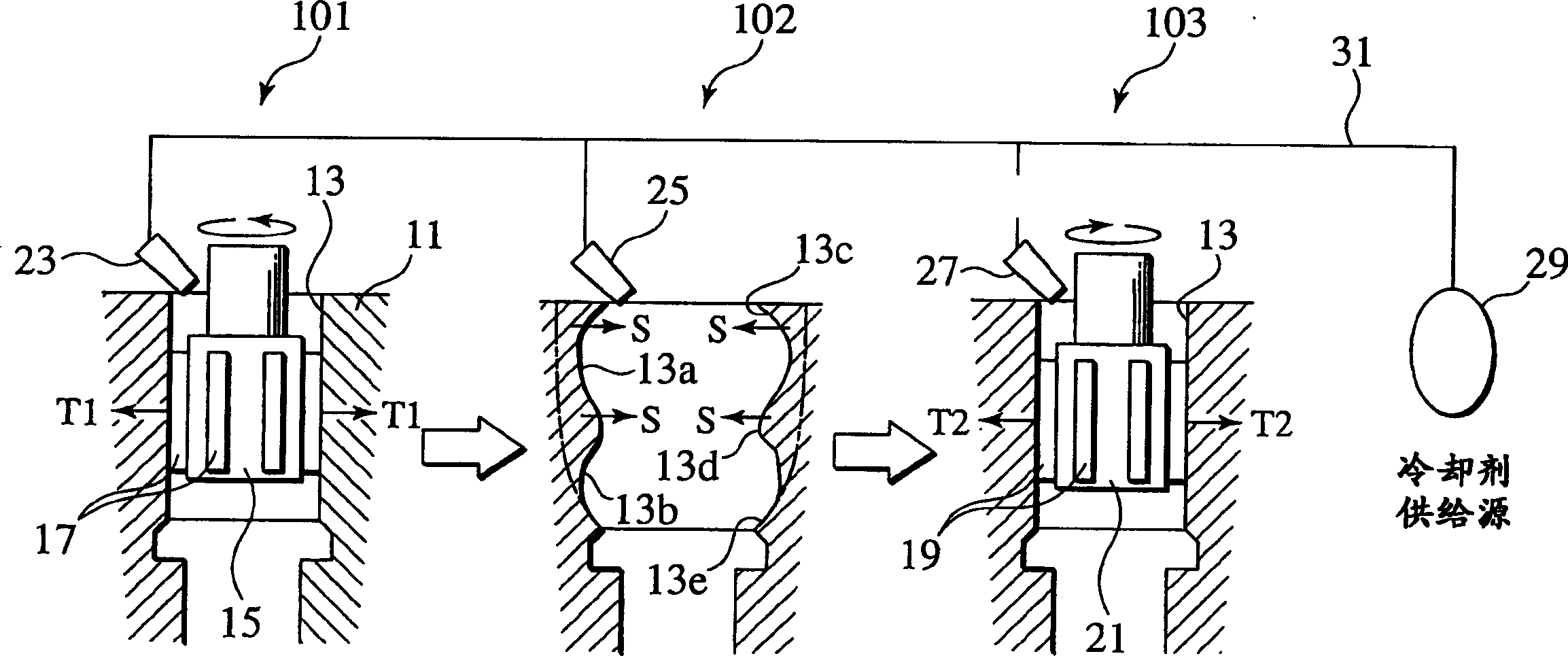
[0030] figure 1 A honing method in one embodiment of the present invention is shown. exist figure 1 In , reference numeral 101 denotes a rough honing step area of ​​the honing method, and 103 denotes a fine honing step area thereof. Also, between the rough honing step area 101 and the fine honing step area 103, an idle step area 102 for leaving the workpiece as it is for a predetermined time ("stand alone time" or "leave time") is provided. ). These step areas are set on the same processing line (working line). An engine cylinder block 11 having a cylindrical inner surface is carried as one workpiece on the processing line in the order of a rough honing step area 101 , an idle step area 102 , and a finish honing step area 103 .

[0031] Such as figure 1 As shown in the rough honing step of , the honing head 15 is inserted into the cylinder bore 13 ...


PUM


Abstract

In a coarse honing step in a section (101), a honing head (15) provided with coarse honing hones (17) is inserted into a cylinder bore (13) of a cylinder block (11), the honing head 15 is rotated while axially moving it, and the inner peripheral surface of the cylinder bore (13) is thereby ground. In the next idling step in a section (102), the cylinder block (11) is left as it is for (60) seconds to generate a springback (S). In a subsequent finishing honing step in a section (103), a honing head (21) provided with finishing honing hones (19) is inserted into the cylinder bore (13), the honing head (21) is rotated in a reverse direction to a rotational direction in the coarse honing step while axially moving it, and the inner peripheral surface of the cylinder bore (13) is thereby ground. Further, a coolant is supplied to the sections of the coarse honing step, the idling step, and the finishing honing step from coolant nozzles (23), (25), and (27), respectively, using a common coolant supply source (29).

Description

technical field [0001] The present invention relates to a honing method and honing apparatus for grinding the inner surface of a workpiece carried on a machining line, the honing is performed by rotating a honing head having a whetstone relative to the workpiece while moving the honing head in the axial direction . Background technique [0002] A workpiece with a cylindrical inner surface, such as the cylinder bore of a cylinder block, is an important area that determines engine performance. For this reason, the inner diameter of the cylinder is required to have high forming accuracy and good surface contour. In terms of molding accuracy, in order to reduce the sliding resistance of the piston, the roundness and cylindricity of the cylinder inner diameter are required to be as high as possible. As for the surface profile, in order to reduce seizure (wear) of the piston, it is desirable to ensure sufficient roughness so that the surface with the cylinder bore has as much oi...

Claims


Application Information

Patent Timeline
Patent Type & Authority Applications(China)
IPC IPC(8): B24B33/02
CPCB24B33/02
Inventor 铃木清久井伊谷隆
Owner NISSAN MOTOR CO LTD
Why Eureka
Try Eureka