Tricot machine

A warp knitting machine and yarn feeding technology, which is applied in the field of warp knitting machines and can solve problems such as high yarn tension

Inactive Publication Date: 2004-04-07
KARL MAYER TEXTILMASCHFAB GMBH
View PDF0 Cites 4 Cited by
  • Summary
  • Abstract
  • Description
  • Claims
  • Application Information

AI Technical Summary

Problems solved by technology

But since a higher force is required to deflect this leaf

Method used


Image

  • Tricot machine
  • Tricot machine
  • Tricot machine

Examples


Example Embodiment

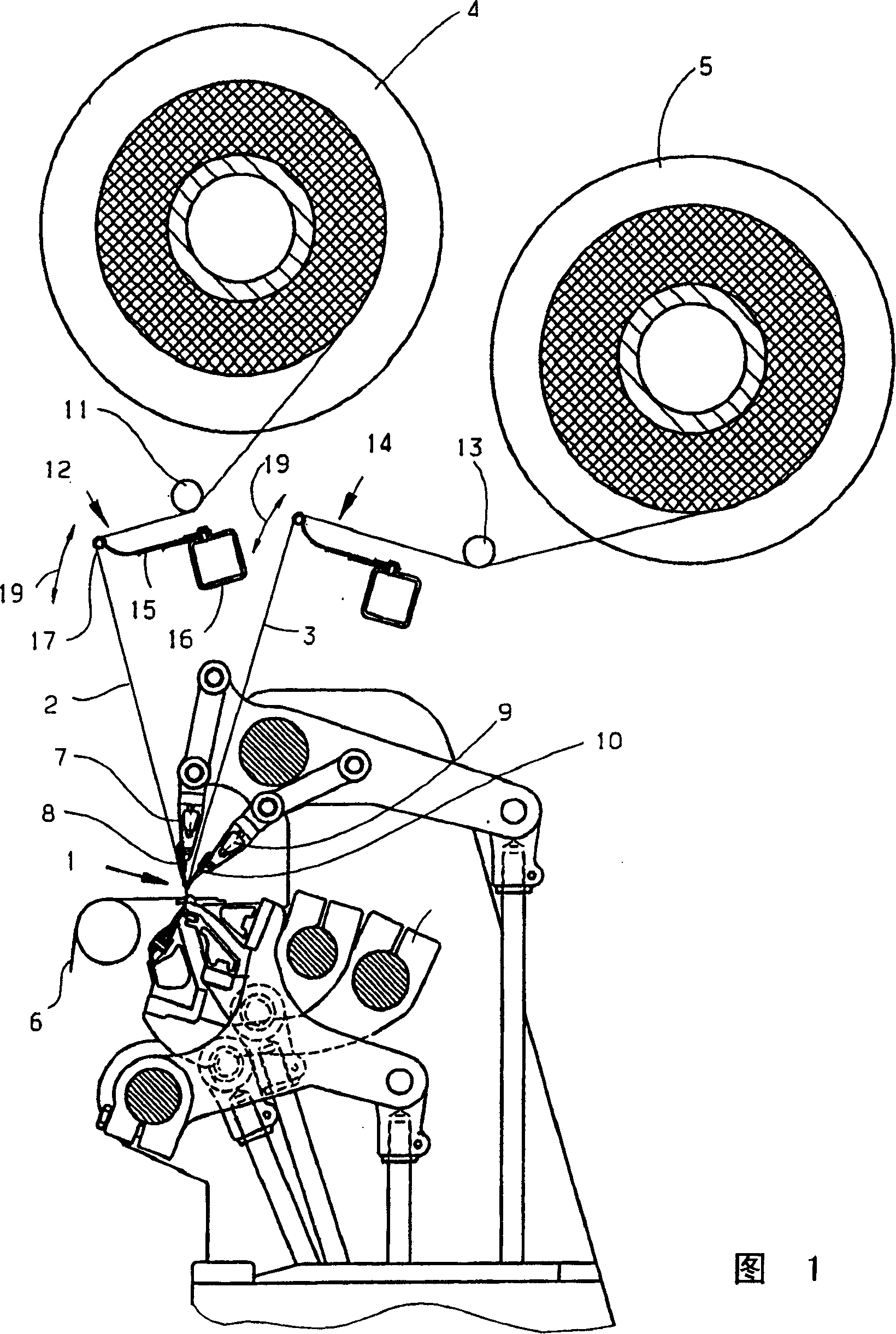
[0032] The warp knitting machine shown schematically and partially in Figure 1 has a knitting work area 1, and yarns 2, 3 are supplied to the knitting work area from warp beams 4 and 5, and the knitted fabric 6 woven from this work area is transported away. . The warp knitting machine has a comb device 7 with comb needles 8 and a comb device 9 with comb needles 10. Between the warp beam 4 and the bar needle 8, the yarn 2 is guided through a fixed guide tube 11 and a yarn tension device 12, on which the yarn is simultaneously deflected. In a similar manner, a guide tube 13 is arranged between the warp beam 5 and the bar needle 10, the guide tube is fixed, and a yarn tension device 14 is behind it. The above-mentioned two yarn tensioning devices are basically the same in structure. Therefore, only the yarn tension device 12 will be described in detail below.

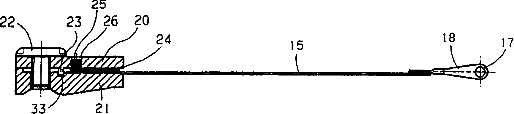
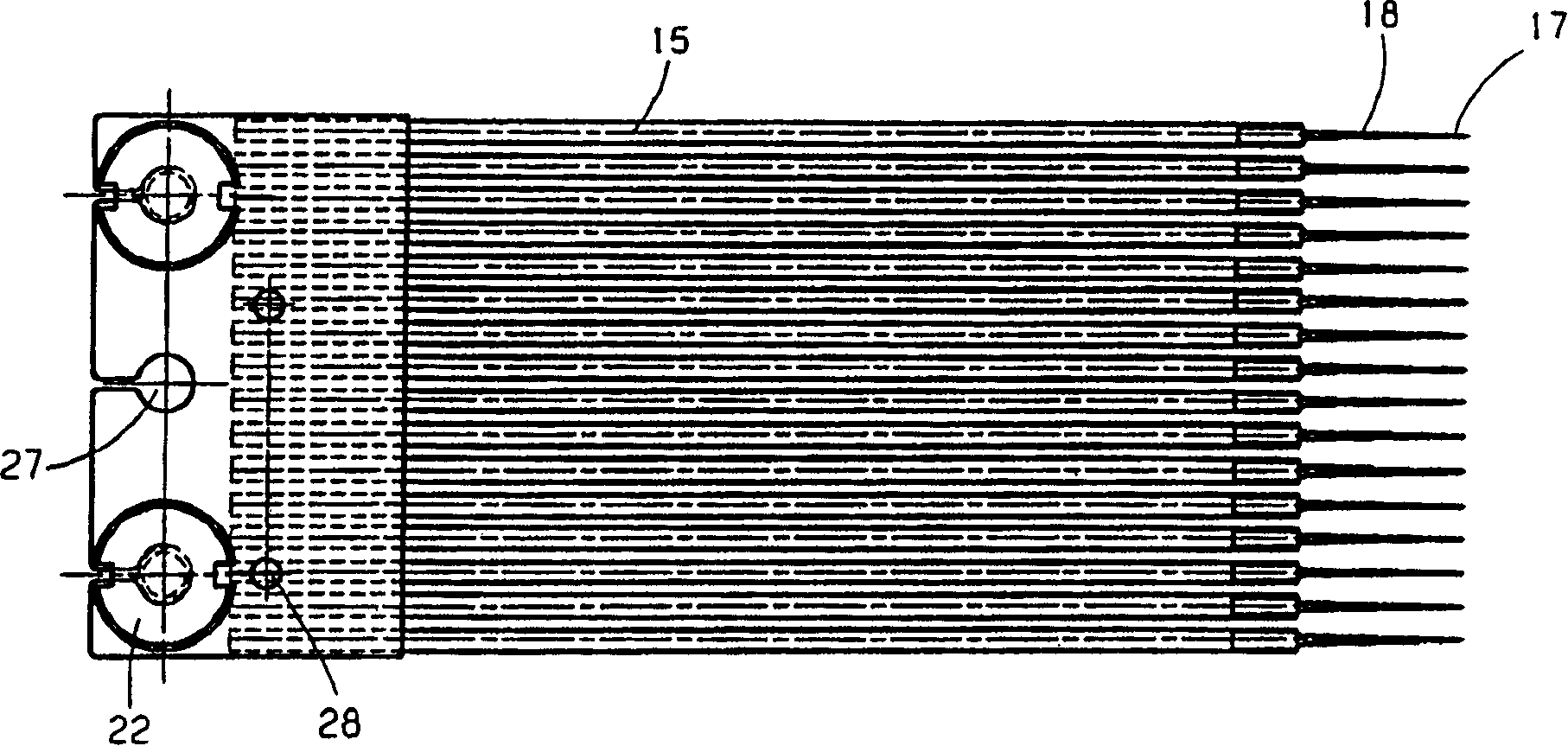
[0033] The yarn tensioning device 12 is equipped with a tension spring 15 for each of the yarns of the warp sheet 2, wherein...


PUM


Abstract

Warp knitting machine having a warping section, a yarn supply section and yarn tension means in which for each yarn is provided a tensioning spring (15) comprising a guiding means (17). Such a warp knitting machine should be operated with a higher speed and enhanced possibilities for patterning. To this end the tensioning spring (15) is made of fiber enforced plastic.

Description

Technical field [0001] The invention relates to a warp knitting machine, which has a knitting zone, a yarn feeding zone and a yarn tension device. The yarn tension device is located between the knitting zone and the yarn feeding zone. A tension spring with a yarn guide device is provided. Background technique [0002] For various warp knitting machines, the yarn consumption is different in a certain period of time. According to the movement of the knitted components, a fluctuating yarn requirement occurs in each knitting cycle. However, at the same time, the warp beam from which the yarn is drawn should rotate as uniformly as possible. In order to be able to accept fluctuations in the amount of yarn required, there is a yarn splitting device that can adjust the length of the distance between the yarn feeding zone and the knitting zone. In this way, fluctuations in the amount of yarn required can be compensated. [0003] On those warp knitting machines that can produce patterns, t...

Claims


Application Information

Patent Timeline
IPC IPC(8): D04B27/14D03D49/04D04B27/10F16F1/368
CPCD04B27/10D04B27/20D04B35/02D04B37/06
Inventor H·-J·赫尼
Owner KARL MAYER TEXTILMASCHFAB GMBH
Why Eureka
Try Eureka