Circuit breaker

A circuit breaker and circuit technology, applied in the field of opening and closing mechanisms, achieves the effects of stable isolation, less restriction, and increased design freedom

Inactive Publication Date: 2004-04-21
FUJI ELECTRIC FA COMPONENTS & SYST CO LTD
View PDF1 Cites 14 Cited by
  • Summary
  • Abstract
  • Description
  • Claims
  • Application Information

AI Technical Summary

Problems solved by technology

[0012] However, as mentioned above, for directly engaging and abutting the notch portion formed on the opening and closing handle, the curved joint member and the link shaft of the toggle linkage mechanism, the shape of the above-mentioned notch portion, the curved joint member, and the shape of the link shaft Position, etc., are subject to many conditions in the design, and are also easily affected by combination accuracy and error. This is the problem.

Method used


Image

  • Circuit breaker
  • Circuit breaker
  • Circuit breaker

Examples


Embodiment Construction

[0025] use below Figure 1 ~ Figure 4 The examples shown illustrate embodiments of the invention. Figures of the examples with Figure 5 The same symbols are used for corresponding parts, and descriptions thereof are omitted.

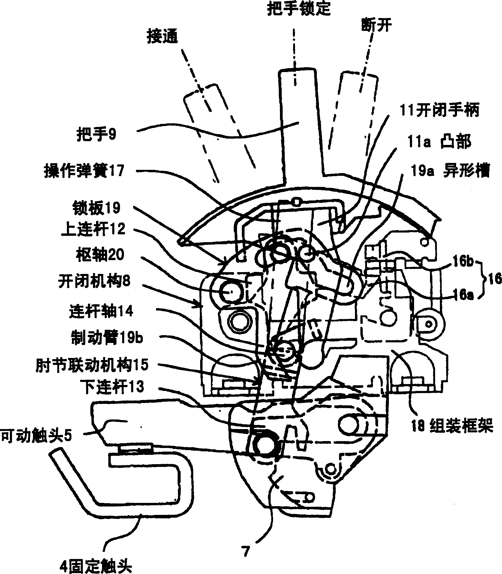
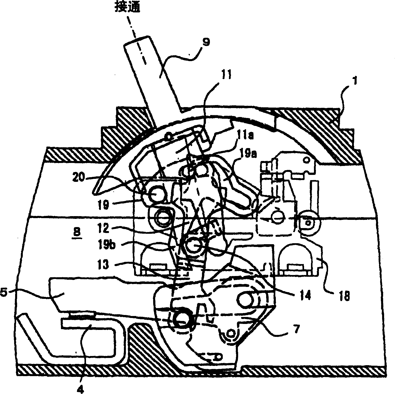
[0026] In the illustrated embodiment, the basic structure of the opening and closing mechanism 8 is the same as Figure 5 Similarly, as a locking part that locks the opening and closing handle 11 and the toggle linkage mechanism 15 to limit the range of movement of the opening and closing handle 11, a lock plate 19 that is an independent part is newly installed.

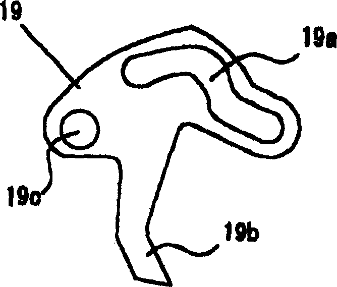
[0027] This lock plate 19 is as figure 2 As shown, the board surface is formed with a "へ"-shaped curved special-shaped groove 19a, a brake arm 19b protruding downward, and a pivot hole 19c pierced at the rear end, as shown in figure 1 As shown, the shown pivot hole 19c is swingably assembled on the assembly frame (side plate) of the opening and closing mechanism 8 through the pivot 20, and...


PUM


Abstract

A circuit breaker includes a movable contact, a fixed contact, a switching device, a switching operation handle, and an over-current tripping device. The switching device has a switching lever connected to the handle, a toggle linkage having an upper link and a lower link for connecting to the movable contact, a tripping mechanism for activating the toggle linkage in response to over-current, and an operation spring tightly stretched between the switching lever and the toggle linkage. A locking member is provided in the switching device for interconnecting the toggle linkage and the switching lever and for restricting a movement range of the switching lever according to an operational position of the toggle linkage. When main-circuit contact points are stuck, the locking member restricts the movement of the switching lever and prevents the handle from moving to the OFF position.

Description

technical field [0001] The present invention relates to a circuit breaker aimed at a wiring circuit breaker, an earth leakage circuit breaker, and the like which are suitable for low-voltage circuits. Specifically, it relates to a switch mechanism having an isolation function for preventing a lever from moving to an OFF position in a state where a main circuit contact is welded due to an abnormal current. Background technique [0002] First, taking the above-mentioned circuit breaker for wiring as an example, the structure of the circuit breaker corresponding to the implementation object of the present invention is shown in Figure 5 . In the figure, 1 is the box body (mold box) of the circuit breaker, 2 is the main circuit terminal on the power supply side, 3 is the main circuit terminal on the load side, 4 is the fixed contact, 5 is the movable contact, and 6 is the Arc suppression device, 7 is the contact supporting seat of the movable contact 5, 8 is the opening and clo...

Claims


Application Information

Patent Timeline
Patent Type & Authority Applications(China)
IPC IPC(8): H01H71/62H01H71/10H01H71/50H01H73/38
CPCH01H71/501H01H71/10
Inventor 三浦正夫满重三弘浅川浩司高桥康弘山县秀人
Owner FUJI ELECTRIC FA COMPONENTS & SYST CO LTD
Why Eureka
Try Eureka