Wireless receiver
A receiving device, radio technology, applied in the direction of selection device, radio/induction link selection arrangement, electrical components, etc., can solve the problem of unable to maintain demodulation signal at high level, unable to compensate DSCH signal fading deviation with high accuracy, etc.
- Summary
- Abstract
- Description
- Claims
- Application Information
AI Technical Summary
Problems solved by technology
Method used
Image

Examples
Embodiment 1
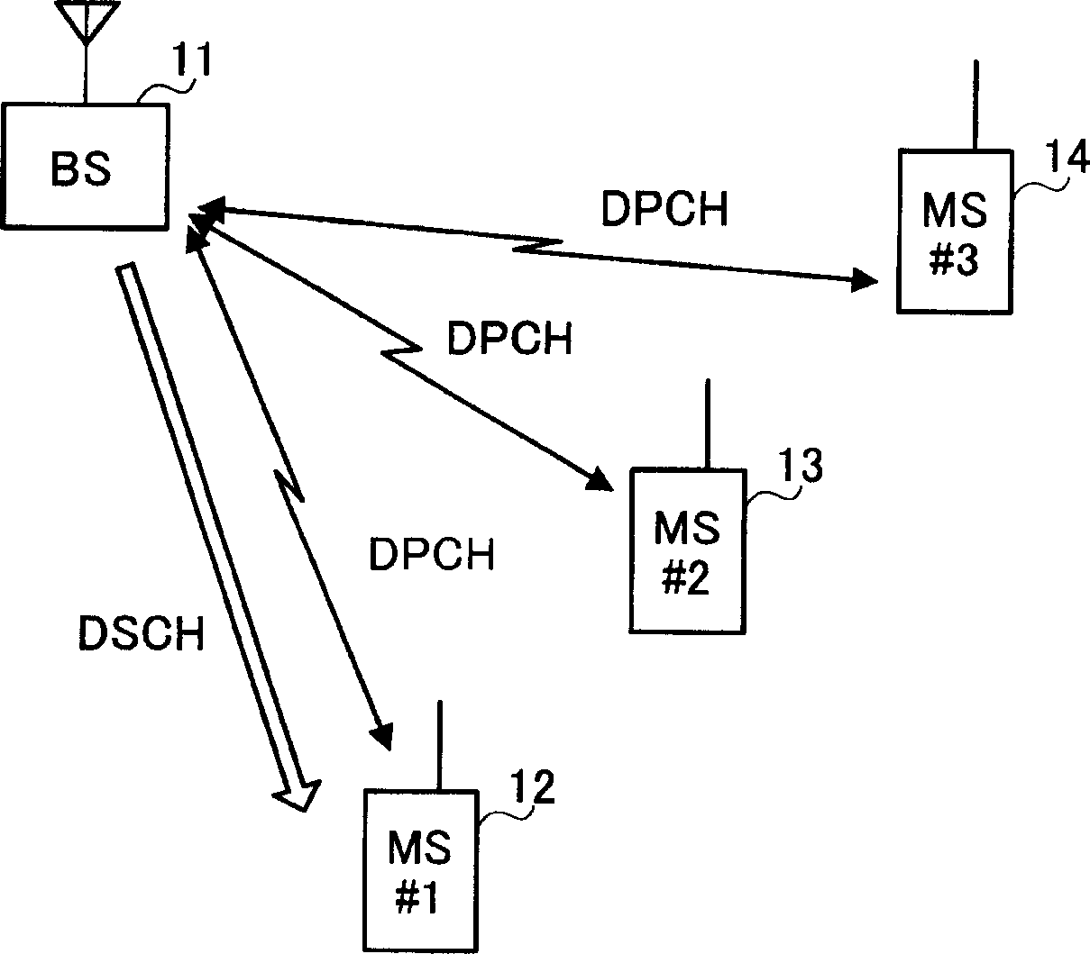
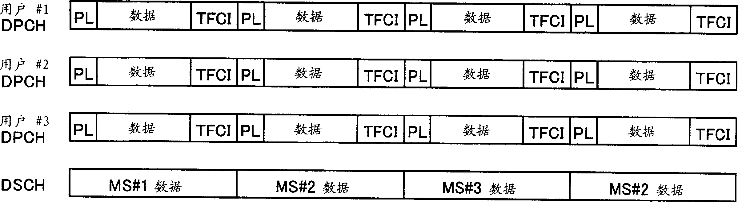
[0023] Here, it will be explained in figure 1 In the mobile communication system of , a mobile station apparatus equipped with a radio receiving apparatus according to the following embodiments is based on figure 2 The channel allocation shown is an example of a case where wireless communication with a base station device is performed.
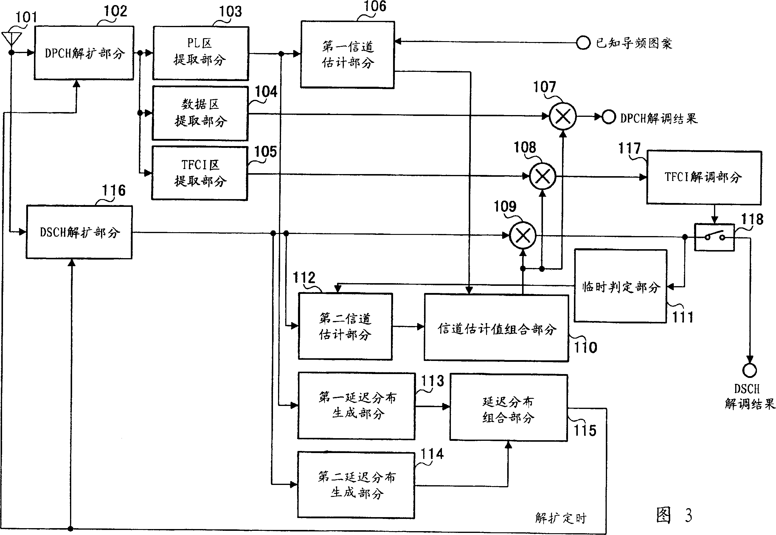
[0024] Fig. 3 is a block diagram showing a mobile station apparatus equipped with a radio receiving apparatus according to Embodiment 1 of the present invention. In FIG. 3, the DPCH despreading section 102 extracts the DPCH by despreading the signal (received signal) received through the antenna 101 at the despreading timing from the delay profile combining section 115 using the spreading code assigned to the mobile station apparatus. signal, the delay profile combining section 115 will be described later.
[0025] The PL region extracting part 103 extracts the known signal ( figure 2 "PL" in ). The data area extraction part 104 extracts...
Embodiment 2
[0057] This embodiment will illustrate an example in which among the received DSCH signals in embodiment 1, only signals exceeding a predetermined threshold are used for channel estimation and generation of delay distribution.
[0058] Embodiment 1 above uses all received DSCH signals for channel estimation and delay profile generation. However, the received DSCH signal includes a signal with reduced power due to the effect of fading. Such a DSCH signal with reduced received power easily includes errors. Performing channel estimation and delay profile generation using such DSCH signals will reduce the accuracy of the extracted demodulated signal.
[0059] Therefore, in this embodiment, only the received DSCH signals exceeding the predetermined threshold are used for channel estimation and delay distribution generation. A radio receiving apparatus according to this embodiment will be described with reference to FIG. 4 .
[0060] 4 is a block diagram showing the configuration...
Embodiment 3
[0065] This embodiment will explain that in the received DSCH signal of Embodiment 1, only DSCH signals based on a modulation system with a small multi-value number of modulation and having received power exceeding a predetermined threshold are used for Channel estimation and delay profile generation.
[0066] Generally, the base station apparatus utilizes the QPSK system (refer to Figure 6A ), 16 QAM system (reference Figure 6B ), 64 QAM system (reference Figure 6C ) to send high-speed data as a DSCH signal. Unless the amplitude information is accurately detected, in the case of receiving DSCH signals having the same average received power, the mobile station apparatus cannot make a correct provisional decision on the DSCH signals using the 16 QAM system and the 64 QAM system, although if only accurately By detecting the phase information, the mobile station apparatus can make an accurate provisional decision on the DSCH signal using the QPSK system.
[0067] Therefore...
PUM
 Abstract
Description
Claims
Application Information
 - R&D Engineer
- R&D Manager
- IP Professional
- Industry Leading Data Capabilities
- Powerful AI technology
- Patent DNA Extraction
Browse by: Latest US Patents, China's latest patents, Technical Efficacy Thesaurus, Application Domain, Technology Topic.
© 2024 PatSnap. All rights reserved.Legal|Privacy policy|Modern Slavery Act Transparency Statement|Sitemap