

Adjustable plane antenna
A planar antenna and plane technology, applied in the directions of antennas, resonant antennas, antenna components, etc., can solve the problems of high antenna manufacturing cost and complicated basic structure of the antenna, and achieve the effect of low additional cost and low growth.
Inactive Publication Date: 2004-04-28
L K PROD OY
View PDF3 Cites 17 Cited by
- Summary
- Abstract
- Description
- Claims
- Application Information
AI Technical Summary
Problems solved by technology
The disadvantage of this solution is that it complicates the basic structure of the antenna, which in this case is relatively expensive to manufacture
Method used
View moreImage
Smart ImageViewing Examples

Examples
no. 2 example
[0017] Figure 5 shows the Figure 4 The effect of the arrangement on the frequency band of antenna operation,
[0018] Figure 6 shows a third example of an adjustable planar antenna according to the invention,
no. 4 example
[0019] Figure 7 shows a fourth example of an adjustable planar antenna according to the present invention, and
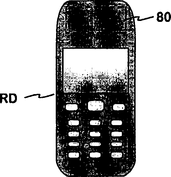
[0020] Figure 8 An example of radio equipment equipped with an antenna according to the invention is shown.
Login to View More PUM
 Abstract
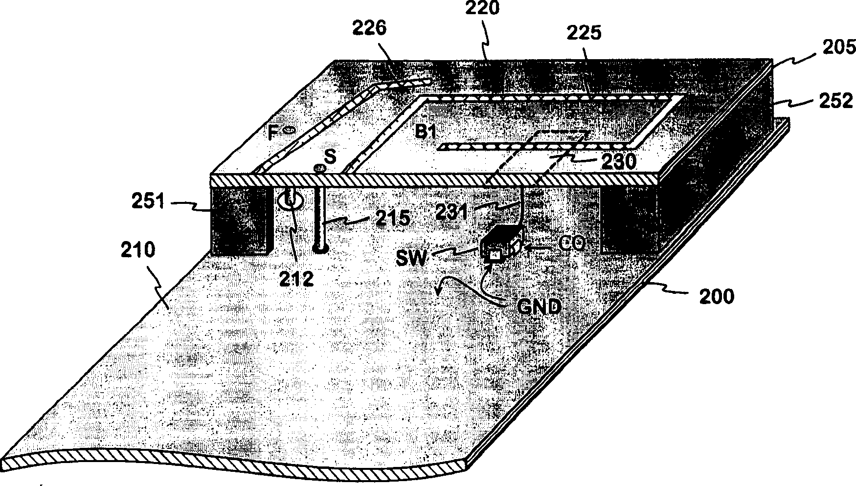
The invention relates to an adjustable planar antenna especially applicable to mobile terminals, and to a radio device provided with that kind of antenna. The basic structure of the antenna is PIFA. On a surface of a dielectric part (205) there is placed a strip conductor (230) so that this has a significant electromagnetic coupling to the radiating plane (220). The strip conductor can be connected by a switch (SW) to the ground plane. When the switch is closed, the electric length of the radiating plane is changed, measured from the short point (S). In which case also the antenna's resonance frequency is changed. The change depends on the place and the size of the strip conductor. In the case of a multi-band antenna the strip conductor can be placed so that it has a remarkable electromagnetic coupling to one or more radiating elements (B1, 226). The adjusting of planar antenna is performed by means of small additive components, which do not presume changes in the antenna's basic structure and do not enlarge the antenna.
Description
technical field [0001] The present invention relates to an adjustable planar antenna especially suitable for mobile terminals. The invention also relates to radio equipment using that antenna. Background technique [0002] In portable radio equipment, especially in mobile terminals, the antenna is preferably placed inside the housing of the equipment for convenience. Internal antennas for small devices are usually of the planar type, since for this antenna it is easiest to achieve satisfactory electrical characteristics. A planar antenna consists of a radiating plane and a ground plane parallel to it. Since mobile terminals are also becoming thinner in thickness, the distance between the radiation plane of the planar antenna and the plane of the plane should be as short as possible. However, the obstacle to reducing the distance is that the bandwidth of the antenna becomes smaller. Then, since mobile terminals are designed to function according to different systems havin...
Claims
Login to View More Application Information
Patent Timeline
 Patent Type & AuthorityApplications(China)
IPC IPC(8): H01Q1/24H01Q5/10H01Q9/04H01Q21/30
CPCH01Q1/243H01Q9/0442H01Q9/0421H01Q21/30
InventorZ·米洛萨杰克
OwnerL K PROD OY