
Method for predicating bundle conductor shift range, predicatin device and program

A range and program technology, applied in the fields of predicting the displacement range of the wire harness, predicting devices and predicting programs, can solve problems such as faults, and achieve the effect of high-precision circuit design

Inactive Publication Date: 2004-05-12
YAZAKI CORP
View PDF0 Cites 2 Cited by
  • Summary
  • Abstract
  • Description
  • Claims
  • Application Information

AI Technical Summary

Problems solved by technology

This can lead to glitches or something like that

Method used

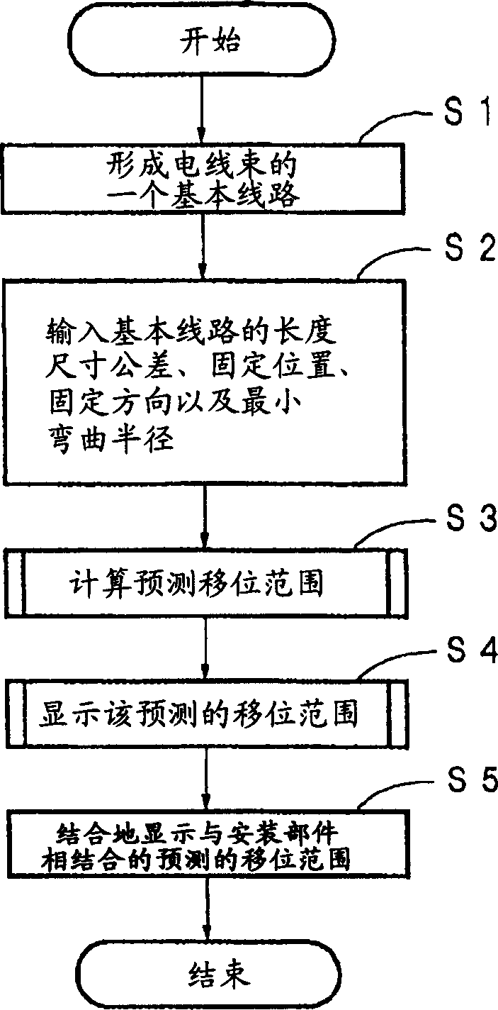

Image

  • Method for predicating bundle conductor shift range, predicatin device and program
  • Method for predicating bundle conductor shift range, predicatin device and program
  • Method for predicating bundle conductor shift range, predicatin device and program

Examples


Embodiment Construction

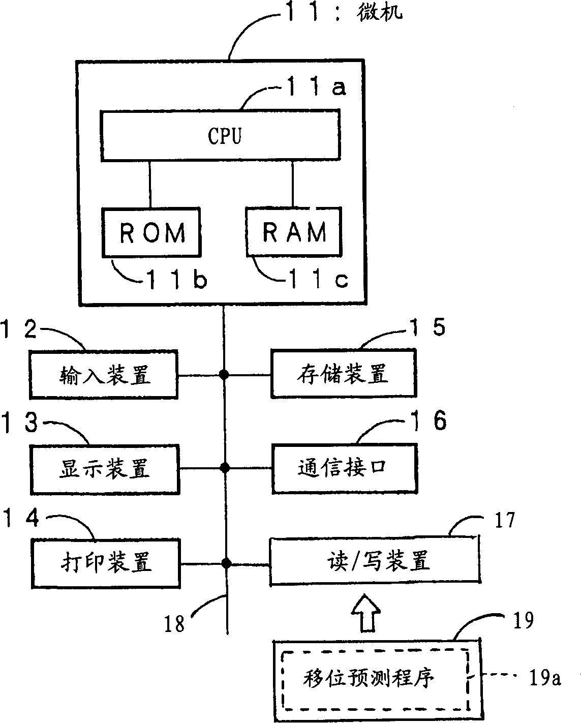
[0035] Preferred embodiments of the present invention will be described with reference to the associated drawings. According to an embodiment of the present invention, the hardware configuration for implementing the shift prediction method will first refer to figure 1 Be explained. figure 1 is a block diagram showing a hardware configuration for executing the present invention.

[0036] Such as figure 1 As shown, the present embodiment uses a computer such as a personal computer, which includes a microprocessor 11 , an input device 12 , a display device 13 , a printing device 14 , a storage device 15 and a communication interface 16 . The microprocessor 11 includes a CPU (central processing unit) 11a, a ROM 11b for storing boot programs and other information, and a RAM 11c for temporarily storing various operation results. The input device 12 as an input unit may be a keyboard, a computer mouse, etc. to input relevant values ​​and other data to the computer. The display de...


PUM

PropertyMeasurementUnit
lengthaaaaaaaaaa

Abstract

A method of predicting a displacement range of a wire harness, includes the steps of: designing a basic route of the wire harness; fixing the wire harness at least two different fixing points on the basic route; computing a displacement range of the wire harness between the fixing points, based on a length of the basic route between the fixing points including a dimensional tolerance, fixing positions and fixing directions of the wire harness at the fixing points, and a minimum bending radius of the wire harness; and displaying the displacement range of the wire harness in three dimensions.

Description

technical field [0001] The present invention relates to a method, device and program for predicting the range of displacement of a wire harness caused by dimensional tolerances, fixing methods, etc., for designing the wiring of a wire harness on a vehicle or the like with high precision. Background technique [0002] Generally, various electronic devices are installed in a vehicle. Those electronic devices are connected by using a wire structure called a wire harness, which is a bundle of wires and communication wires bundled together by insulating locking tape, insulating tape, or the like. Generally, the wire harness is designed in consideration of the shape of the door, body, etc. of the vehicle to which the wire harness is to be installed, the number of electronic parts, the distribution of the wire harness on the panel of the wire harness installation tool, and other factors. [0003] The wiring harness thus routed and installed at the intended location sometimes cause...

Claims


Application Information

Patent Timeline
Patent Type & Authority Applications(China)
IPC IPC(8): H01B13/00B60R16/02G06F17/50H01B13/012H02G3/00H02G3/38
CPCB60R16/0207H01B13/00
Inventor 土屋信治长谷川武司岛田智
Owner YAZAKI CORP
Learn More