Disk device

A roller and frame technology, applied in recording information storage, instruments, etc., can solve problems such as poor action and increase action load, and achieve the effect of reducing contact area, preventing the increase of action load, and smooth insertion and removal

Inactive Publication Date: 2004-05-19
MITSUBISHI ELECTRIC CORP
View PDF0 Cites 0 Cited by
  • Summary
  • Abstract
  • Description
  • Claims
  • Application Information

AI Technical Summary

Problems solved by technology

[0004] However, since the above-mentioned disk device has the above-mentioned structure, when the bonded disk is inserted into and removed from the disk device, when the contact portion of the disk comes into contact with the outer peripheral surface of the bonded disk, the adhesive leaked from the outer peripheral surface will be formed. The friction generated between the contact surfaces increases the operating load, so there is a problem that the bonded disk cannot be inserted and removed smoothly, and in the worst case, it may cause malfunction.

Method used


Image

  • Disk device
  • Disk device
  • Disk device

Examples


Embodiment Construction

[0020] Next, embodiments of this invention will be described.

[0021] Implementation form 1.

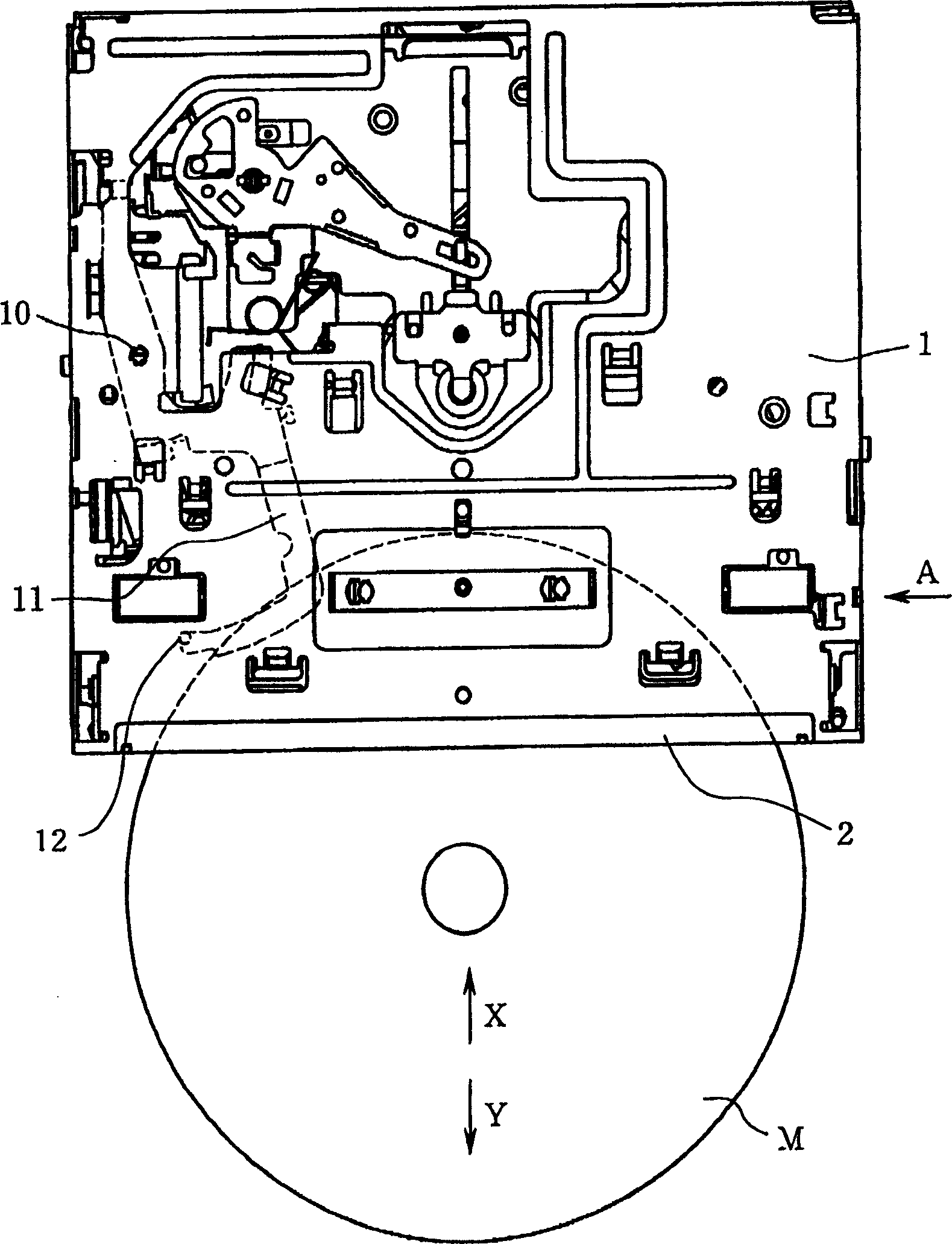
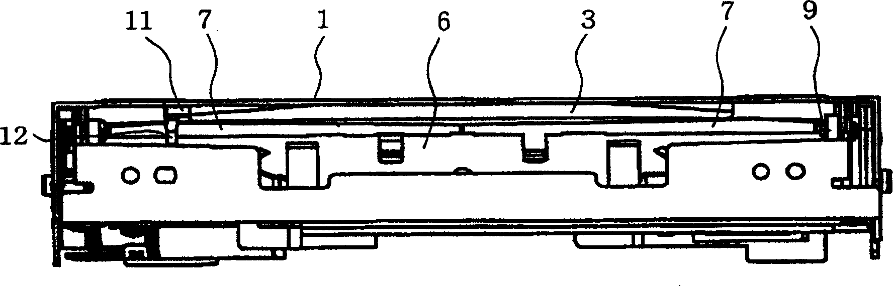
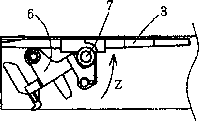
[0022] figure 1 is a plan view showing the internal structure of the disk device according to Embodiment 1 of the present invention, figure 2 yes means figure 1 Front view of the disk device shown, image 3 It is seen when viewed from the direction of arrow A figure 1 A side view of the internal structure of the disk device shown, Figure 4 yes means Figure 1 to Figure 3 An illustration of the structure of the guide member of the disc device, Figure 4 A is the floor plan, Figure 4 B is the front view, Figure 5 It is viewed from the direction of arrow B Figure 4 An enlarged view of the main part of the guide member shown, Figure 6 yes means Figure 1 to Figure 3 A plan view of the structure of the roller support member of the disc device shown, Figure 7 It is viewed from the direction of arrow C Figure 6 The enlarged view seen when the main part of the roller su...


PUM


Abstract

A guide flap 3 is nearly a flat member, and a pair of disk guide parts 4, 5 is formed at its both sides. Each inside of the disk guide parts 4, 5 is abutted on an outer periphery of the disk M to form disk abutting parts 4a, 5a for supporting it. The disk abutting part 4a is formed into the uneven shape having a plurality of grooves extended in the direction of the thickness of the disk M.

Description

【Technical field】 [0001] BACKGROUND OF THE INVENTION Field of the Invention The present invention relates to a disc device for optically recording and reproducing video and audio information, etc., on a disc such as a DVD (Digital Video Disc). 【Background technique】 [0002] A disk device for recording and reproducing disks such as DVDs, including: a frame with a disk insertion slot, guide pieces fixed near the insertion slot of the frame, and guiding the disk, and provided between the guide pieces to be guided. The rollers with high disk transport force, the roller seat supporting the rollers, and the disk size selection lever for judging the size of the disk. On the guide piece, the roller base and the disk size selection lever, there are disk contact portions that contact and support the outer peripheral surface of the disk at positions facing the disk conveyance path. The contact portion of each disk in the conventional disk device has a surface that contacts in the thi...

Claims


Application Information

Patent Timeline
Patent Type & Authority Applications(China)
IPC IPC(8): G11B17/051G11B17/04
CPCG11B17/051
Inventor 伊东成浩
Owner MITSUBISHI ELECTRIC CORP
Why Eureka
Try Eureka