Foldable chair support
A chair support frame and support frame technology, which is applied in the field of folding chair support frames, can solve the problems of the support frame losing its center of gravity and falling, and the connecting piece is easy to pinch the human body, etc., so as to achieve the effect of stable opening state and safe use
- Summary
- Abstract
- Description
- Claims
- Application Information
AI Technical Summary
Problems solved by technology
Method used
Image

Examples
Embodiment 1
[0021] Example 1 ( Figure 2 to Figure 5 )
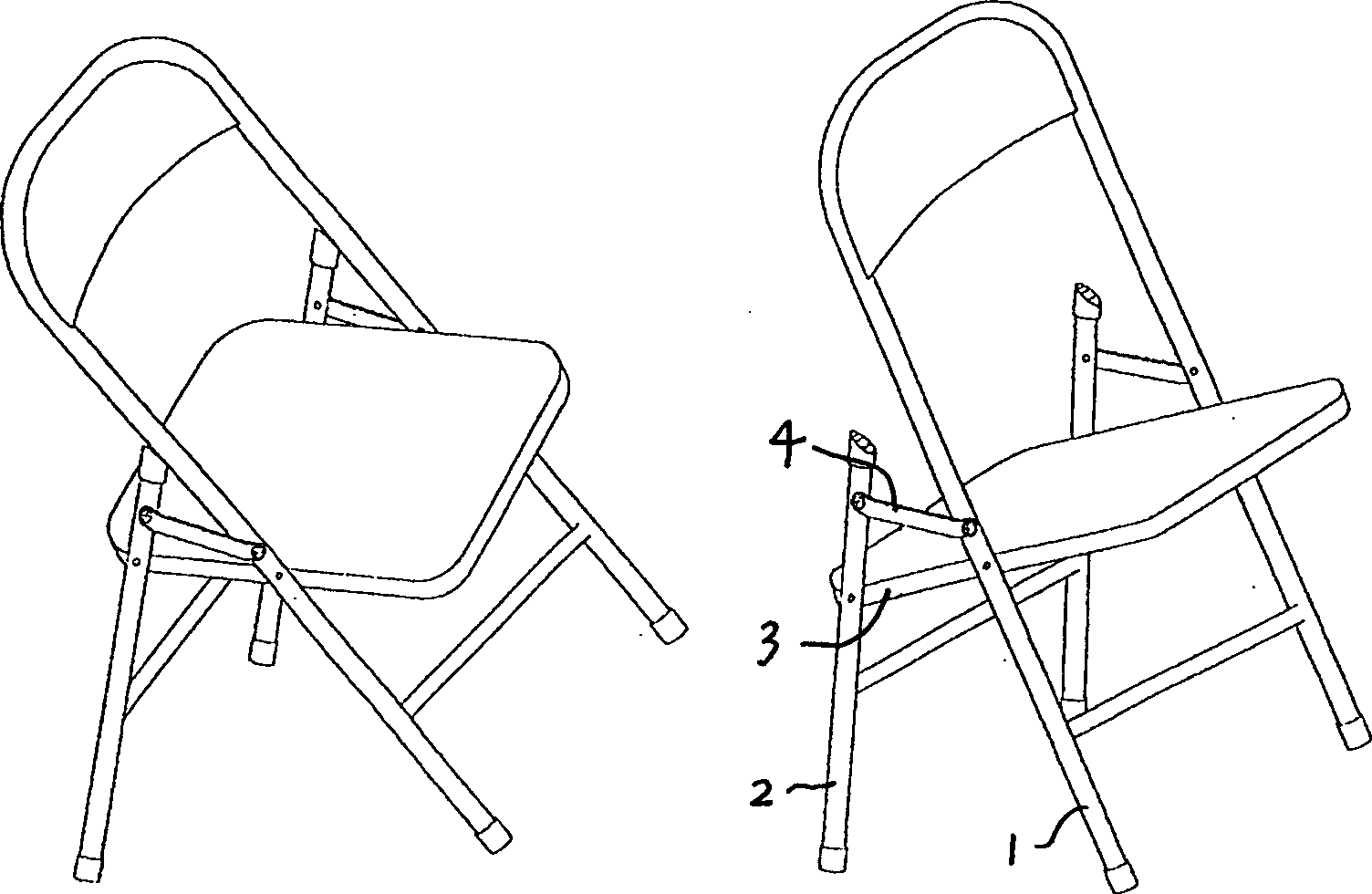
[0022] The left and right sides of this example are respectively hinged by the front and rear leg bars, the chair surface support bar, and the backrest bar. The middle part is hingedly connected with the sliding sleeve 5 which is set on the chair support bar 3 in a dynamic fit; Cover 5 is hingedly connected with the position between the hinge point of the front leg bar, and the armrest bar 8 front portion is hingedly connected with the front leg bar 1 upper end, and the seat surface support bar 3 rear ends are provided with sliding sleeve limit parts.
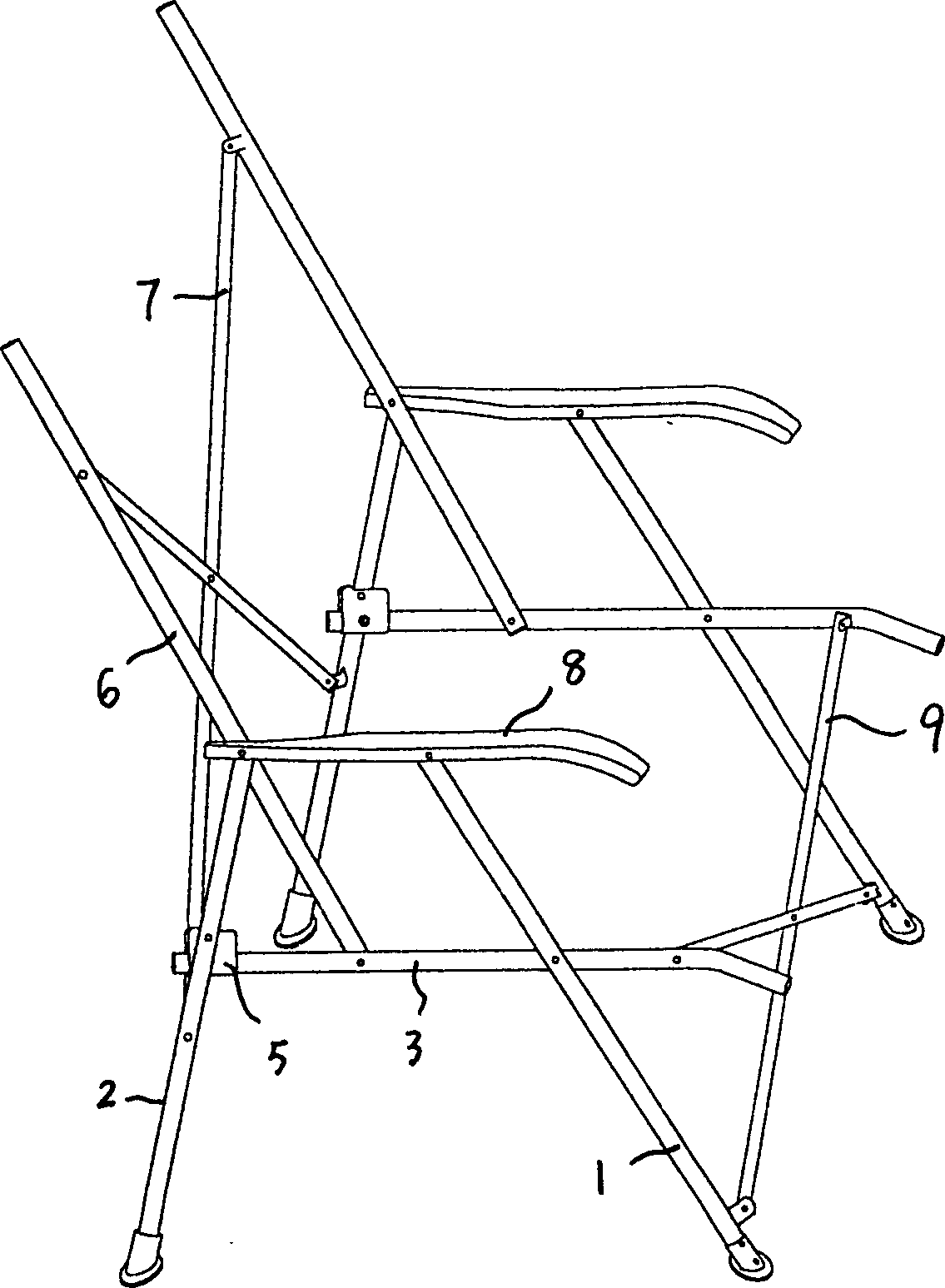
[0023] Horizontal support parts 7 and 9 are arranged between the support frames on both sides, wherein the horizontal support part 9 is composed of an X-shaped bracket formed by hinge connection in the middle of two support rods, and the two ends of the upper part of the X-shaped bracket are connected with the chair surface support rods on both sides respectively. 3. The front part...
Embodiment 2
[0025] Example 2 ( Image 6 , Figure 7 )
[0026] The structure of the supporting frame that the left and right sides of this example are connected by the front and rear leg bars, the chair surface support bar and the backrest bar hinge respectively is: the front leg bar 1 is connected with the middle part of the seat surface support bar 3 hinges, and the backrest bar 6 is hinged by an oblique The front leg bar 1 is formed by the extension part backward and upward, the rear leg bar 2 middle part is hingedly connected with the sliding sleeve 5 which is dynamically fitted on the seat support bar 3, and the rear leg bar 2 upper ends are hingedly connected with the backrest bar 6 .
[0027] Horizontal support parts 7 and 9 are arranged between the support frames on both sides, wherein the structure of the horizontal support part 9 is the same as that of Embodiment 1, and the upper and lower ends of the X-shaped bracket form armrests from the upward curved extensions at the hinge...
Embodiment 3
[0028] Embodiment 3 ( Figure 8 , 9 、10)
[0029] The left and right sides of this example are respectively hinged by the front and rear leg bars, chair surface support bar, and backrest bar. The middle part is hingedly connected with the sliding sleeve 5 which is set on the chair surface support rod 3 in a dynamic fit, the front leg rod 1 upper end is hingedly connected with the hinge head 11 fixed on the rear leg rod 2 upper end, and the backrest rod 6 lower end is connected with the chair surface support rod 3 The rear end is hingedly connected, the rear end of the armrest rod 8 is hingedly connected with the backrest rod 6, and the hinge head 11 at the upper end of the rear leg rod 2 is longitudinally slidably connected with the armrest rod 8. The sliding connection structure is: the upper hinge of the hinge head 11 is hingedly connected with a sliding connection part 12, see Figure 8 , 9 , the sliding connection part 12 is movably embedded in the longitudinal chute 8...
PUM
 Abstract
Description
Claims
Application Information
 - R&D
- Intellectual Property
- Life Sciences
- Materials
- Tech Scout
- Unparalleled Data Quality
- Higher Quality Content
- 60% Fewer Hallucinations
Browse by: Latest US Patents, China's latest patents, Technical Efficacy Thesaurus, Application Domain, Technology Topic, Popular Technical Reports.
© 2025 PatSnap. All rights reserved.Legal|Privacy policy|Modern Slavery Act Transparency Statement|Sitemap|About US| Contact US: help@patsnap.com