External limb fixing frame special for orthopedic department

A fixed frame and limb technology, applied in the field of medical devices, can solve the problems of simple style, single function, and unsatisfactory, and achieve the effect of convenient operation, firm connection, and meeting the requirements of firmness and accuracy

Inactive Publication Date: 2019-10-18
FUJIAN PROVINCIAL HOSPITAL
View PDF7 Cites 2 Cited by
  • Summary
  • Abstract
  • Description
  • Claims
  • Application Information

AI Technical Summary

Problems solved by technology

[0003] With the expansion of external limb fixation in clinical applications, there are more and more styles of external limb fixation frames. However, most of the existing external limb fixation frames are simple in style and single in function, which cannot meet the requirements of firmness, convenience and ease of fixation. Operability and other aspects of the demand, for this we have introduced a special orthopedic external limb fixation frame

Method used


Image

  • External limb fixing frame special for orthopedic department
  • External limb fixing frame special for orthopedic department
  • External limb fixing frame special for orthopedic department

Examples


Embodiment 1

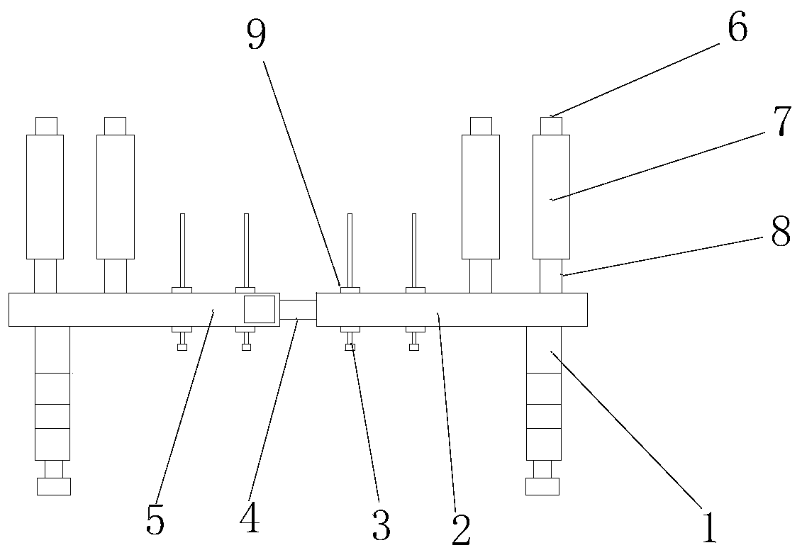
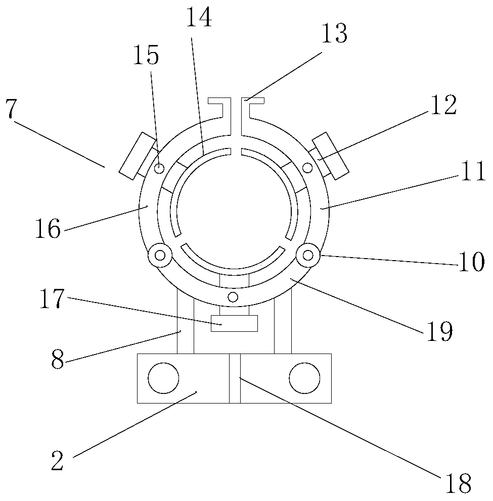
[0027] see Figure 1-4 , a special external limb fixation frame for orthopedics, including a first support plate 2 and a second support plate 5 symmetrically arranged on both sides, the left end of the first support plate 2 and the right end of the second support plate 5 are connected by two screw rods 4 connection, the lower right end of the first support plate 2 and the lower left end of the second support plate 5 are respectively provided with fixed feet 1, the upper right end of the first support plate 2 and the lower end of the second support plate 5 The left end upper side is provided with two limb fixing rings 7 respectively, and the lower end of described fixing ring 7 is all fixed on the first support plate 2 or the second support plate 5 by connecting rod 8, the left end of described first support plate 2 and The right end of the second supporting plate 5 is respectively penetrated with two fixing nails 3; the fixing ring 7 comprises a first fixing plate 11, a second...

Embodiment 2

[0028] Embodiment two: this embodiment adds the following technical solutions on the basis of embodiment one:

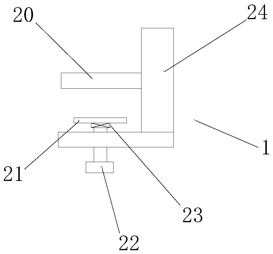
[0029] see image 3 Described fixed foot 1 comprises L-shaped plate 24 and transverse plate 20, and the upper end of described L-shaped plate 24 is connected with the lower end of support plate, and one end of described transverse plate 20 is fixedly connected on the inner side of L-shaped plate 24, and L-shaped plate The middle of the lower end of 24 is threaded through and connected with tightening screw 22, and the upper end of tightening screw 22 is connected on the inner ring of bearing 23, and the outer ring of bearing 23 is fixedly connected on the splint 21, when a fixing device is needed, the horizontal plate 20 and splint 21 are respectively placed on both sides of the fixture, and the screw 22 is rotated clockwise, and the splint 21 is close to the horizontal plate 20, and the fixture is clamped. When the device is disassembled, the screw 22 is turned coun...

Embodiment 3

[0030] Embodiment three: this embodiment adds the following technical solutions on the basis of embodiment two:

[0031] Two limit nuts 9 are arranged on the fixing nail 3, and the limit nuts 9 are located on the upper and lower sides of the first support plate 2 and the second support plate 5. When a dislocation fracture of a limb needs to be fixed, first The upper and lower ends of the fractured limb are fixed by the fixing ring 7, after the fixation nail 3 passes through the bones at both ends of the misalignment to correct the position, and then the limit screw 15 is tightened, and the screw sleeve 27 is adjusted at the same time to keep the two support plates at an appropriate distance ;


PUM


Abstract

The invention discloses an external limb fixing frame special for the orthopedic department. The external limb fixing frame comprises a first supporting plate and a second supporting plate which are symmetrically arranged at the two sides, the left end of the first supporting plate and the right end of the second supporting plate are connected through two lead screws, fixing legs are arranged at the lower side of the right end of the first supporting plate and the lower side of the left end of the second supporting plate respectively, two limb fixing rings are arranged at the upper side of theright end of the first supporting plate, and two limb fixing rings are arranged at the upper side of the left end of the second supporting plate. The external limb fixing frame is reasonable in layout and ingenious in structure, the whole device is fixed to a proper position through the fixing legs, then the limbs are supported through the two supporting plates, the four fixing rings are adoptedfor clamping the two ends of each required limb, then fixing nails penetrate through staggered bone at the two ends for after-position-correction fixation, and limiting screws are screwed up; meanwhile, a screw cover is adjusted to keep a proper distance between the two supporting plates, the requirement of limb fixation for the firmness and precision of the frame is met, and the operation is convenient.

Description

technical field [0001] The invention relates to the technical field of medical devices, in particular to a special external limb fixation frame for orthopedics. Background technique [0002] External limb fixation refers to the use of external fixators to treat limb fractures. Over the years, its indications have mainly included patients with infected open fractures, skin loss that cannot be covered by phase I, or internal fixation that cannot achieve stable fixation. With the strengthening of the awareness of trauma, the indications for its clinical application are gradually expanding; external limb fixation can also prevent secondary damage caused by the broken end of the fracture stabbing blood vessels, nerves and other surrounding tissues, and reduce pain, which is convenient for rescue transportation and handling. [0003] With the expansion of external limb fixation in clinical applications, there are more and more styles of external limb fixation frames. However, most...

Claims


Application Information

Patent Timeline
Patent Type & Authority Applications(China)
IPC IPC(8): A61B17/60A61B17/66
CPCA61B17/60A61B17/66A61B2017/564
Inventor 周仕国
Owner FUJIAN PROVINCIAL HOSPITAL
Why Eureka
Try Eureka