Foldable chair support
A chair support frame and support frame technology, applied in the field of folding chair support frames, can solve the problems that the connecting piece is easy to pinch the human body, the support frame loses its center of gravity and falls, and achieves the effect of stabilizing the opened state and prolonging the service life
- Summary
- Abstract
- Description
- Claims
- Application Information
AI Technical Summary
Problems solved by technology
Method used
Image

Examples
Embodiment 1
[0028] Embodiment 1 (Fig. 2~ Figure 7 )
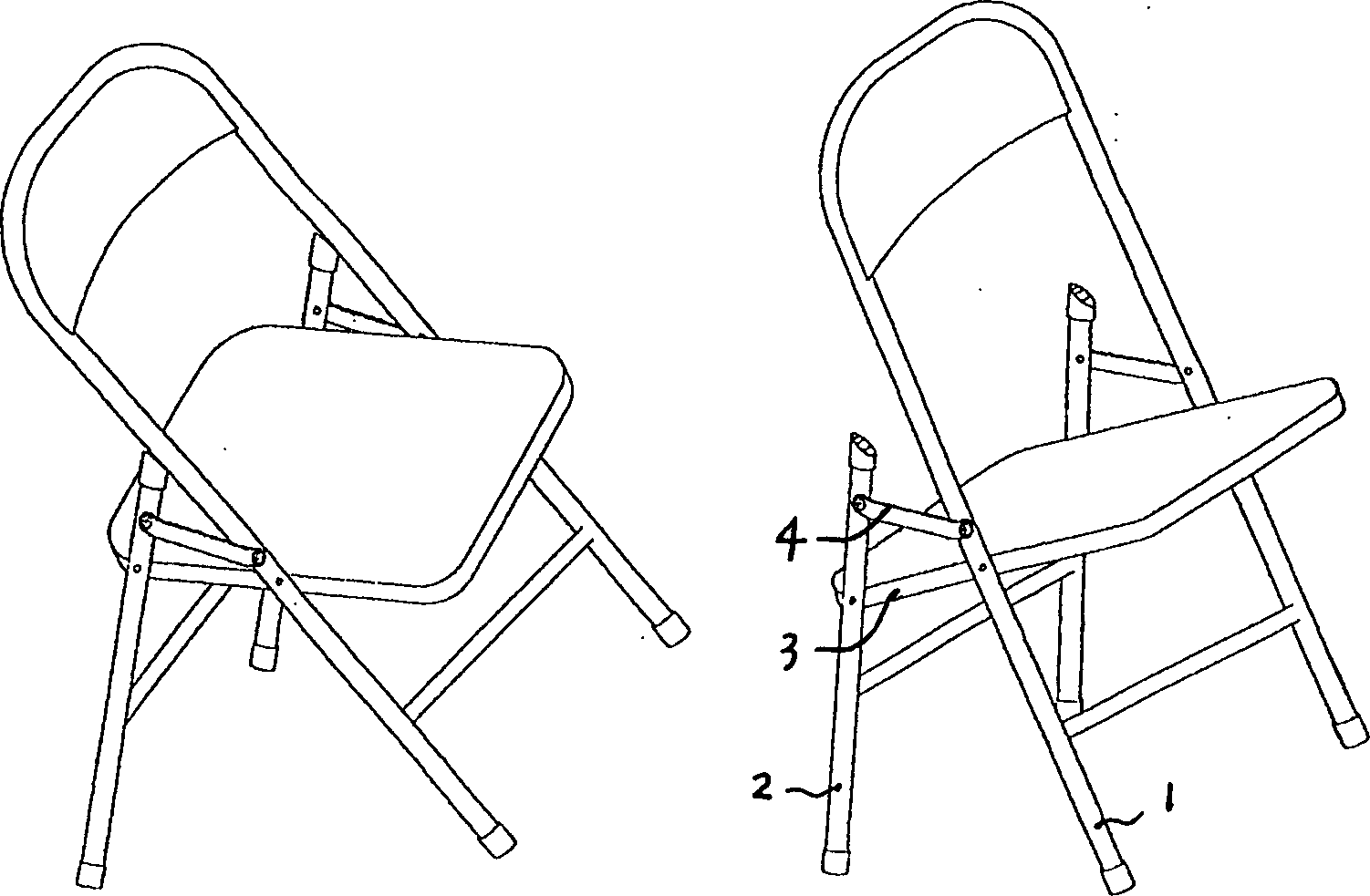
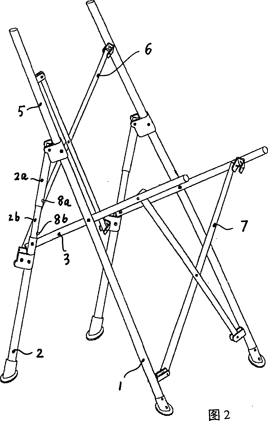
[0029] The structure of the support frame on the left and right sides of this example is: the front leg rod 1 and the rear leg rod 2 are hingedly connected with the chair surface support rod 3 respectively, and the oblique front leg rod 1 is backward from its hinge with the chair surface support rod 3 The top extends to form a back bar 5 , and the upper ends of the telescopic bar bodies 2 a and 2 b on the top of the rear leg bar 2 are hinged to the back bar 5 .
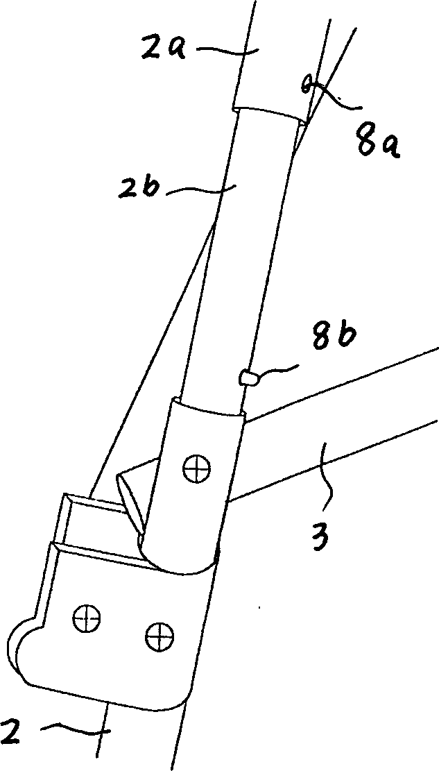
[0030] See image 3 In this example, a locking device 8 is provided between the inner tube 2b and the outer tube 2a of the telescopic rod body. When the support frame is stretched and the outer sleeve and the inner tube are retracted to the closed position, the elastic contact springs into the locking hole to lock the outer sleeve and the inner tube to each other, making the expanded support frame more stable. When it needs to be folded, Press the elastic button to disenga...
Embodiment 2
[0033] Example 2 ( Figure 8 , Figure 9 )
[0034] The structure of the support frames on the left and right sides of this example is the same as that of Embodiment 1, the difference is that the horizontal support components arranged between the left and right sides of the support frames are non-folding structures: hard Chair surface 10, hard chair surface 8 are not only the chair surface, but also the lateral support member, and cross bar is respectively fixed with cross bar to form lateral support member 6,7,9 between the backrest bar of both sides and front and rear leg bar.
[0035] The difference from Example 1 is that when folding in this example, only the support rods of the chair surface can be folded upwards and backwards so that the front and rear leg rods are moved closer together, and the support frames on the left and right sides cannot be moved closer to the middle
Embodiment 3
[0036] Embodiment 3 ( Figure 10 , 11 )
[0037] The structure of the support frame on the left and right sides of this example is: the chair surface support rod 3 is hingedly connected with the front and rear leg rods respectively, and the lower end of the backrest rod 5 is hinged with the position between the seat surface support rod 3 and the hinge point of the front and rear leg rods. , the upper end of the telescopic rod body on the upper part of the rear leg rod 2 is hinged to the backrest rod 5 and the rear end of the armrest rod 11, and the upper end of the front leg rod 1 is hinged to the front part of the armrest rod 11 from the hinge of the front leg rod 1 and the chair support rod 3. connect.
[0038] Horizontal supporting parts 7, 6 are arranged between the supporting frames on both sides, and its structure is the same as that of Embodiment 1.
PUM
 Abstract
Description
Claims
Application Information
 - R&D Engineer
- R&D Manager
- IP Professional
- Industry Leading Data Capabilities
- Powerful AI technology
- Patent DNA Extraction
Browse by: Latest US Patents, China's latest patents, Technical Efficacy Thesaurus, Application Domain, Technology Topic.
© 2024 PatSnap. All rights reserved.Legal|Privacy policy|Modern Slavery Act Transparency Statement|Sitemap