Hole plug

A hole plug and head technology, applied to nuts, superstructure sub-assemblies, applications, etc., can solve problems such as unreliable insertion operations, and achieve the effects of easy insertion, restraining radial shrinkage, and improving sealing performance

Inactive Publication Date: 2004-06-02
NIFCO INC
View PDF1 Cites 8 Cited by
  • Summary
  • Abstract
  • Description
  • Claims
  • Application Information

AI Technical Summary

Problems solved by technology

However, when such a structure is adopted, since the separation leg is easy to bend, there is a concern that a part of the separation leg will be lifted by the effect of the hole peripheral part during insertion, and a part of the separation leg cannot be inserted into the hole. The other separation pins are inserted, and the insertion work may not be performed reliably

Method used


Image

  • Hole plug
  • Hole plug
  • Hole plug

Examples


Embodiment Construction

[0027] Hereinafter, embodiments of the present invention will be described with reference to the drawings.

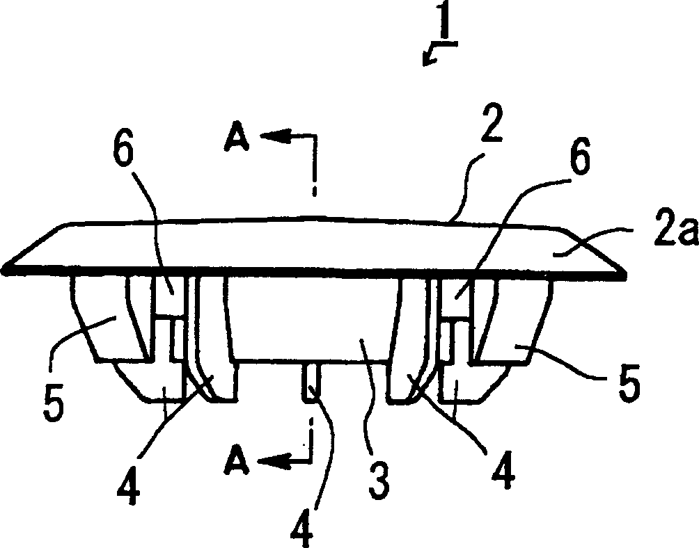
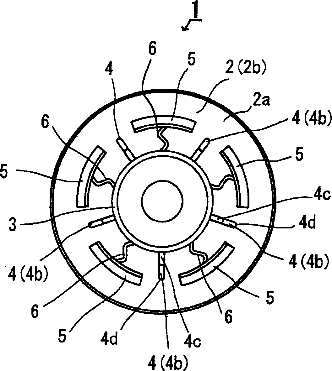
[0028] exist Figure 1 ~ Figure 4 Among them, symbol 1 is the hole plug of this embodiment, and the hole plug 1 has: a head 2, a pillar portion 3, a plurality of (5 in this embodiment) guide portions 4, and a plurality of foot portions. (5 in this embodiment) upright plate portions, a plurality of (5 in this embodiment) support portions 6 as support means, and these members 2 to 6 are integrally molded using synthetic resin such as polyethylene.

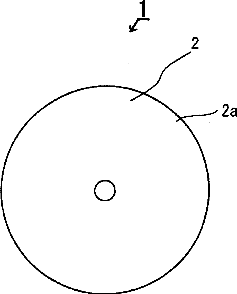
[0029] The head portion 2 is formed in a thin disc shape. Most of the head 2 is flat except for the peripheral portion 2a, which can be given elasticity by bending and is inclined toward the inner surface 2b side as it goes radially outward of the head 2.

[0030] The said pillar part 3 stands upright from the inner surface 2b of the said head part 2. As shown in FIG. The pillar portion 3 is formed in a cylindrical shape fr...


PUM


Abstract

There is provided with a head 2 and a foot which is inserted into the hole 11 to be choked. The foot is formed in a cylindrical shape with a plurality of erecting tabular plates 5 erecting from a rear face 2b of the head. An engagement step 8 sandwiching an hole periphery 10a is formed with the head 2 at a base end 5a of each erecting plate 5. This process makes it easy to make each erecting plate 5 flex on inserting, and only head periphery 2a is bent around the hole periphery 10a when the hole periphery 10a is sandwiched by the engagement step 8 and the head periphery 2a. Moreover, a pillar 3 is integrally erected at the rear face 2b of the head. The pillar 3 is connected to each erecting plate 5 with each supporting part 6 so as to reinforce the engagement relationship with the hole periphery 10a at each engagement step 8 of each erecting plate 5.

Description

technical field [0001] The present invention relates to a hole plug for sealing a hole formed in a plate such as a steel plate used in various products such as automobiles. Background technique [0002] The hole plug basically has a head and a leg protruding from the inner surface of the head so as to be inserted into the plugged hole. Recently, as disclosed in Patent Document 1, as such a plug, from the viewpoint of aesthetics, the head is not opened on the upper surface but is made slightly flat, and on the other hand, the legs are made from the viewpoint of ease of insertion. The foot part is composed of a foot body protruding from the inner surface of the head, and a plurality of claws that are turned back from the front end of the foot body to the head side, and each claw can be connected to the front end of the foot body. The foot portion is a fulcrum that expands and contracts (swings) along the radial direction of the foot body. According to this structure, when th...

Claims


Application Information

Patent Timeline
Patent Type & Authority Applications(China)
IPC IPC(8): F16B37/14B62D25/24
CPCY10T24/309B62D25/24
Inventor 长泽德昌大林升
Owner NIFCO INC
Why Eureka
Try Eureka