Ink feed regulator for ink feeder

A volume adjustment and ink feeding technology, which is applied to the general parts of printing machinery, printing, printing machines, etc., can solve the problems of increased cost, increased number of parts, inconvenience, etc., and achieve the effect of reducing the number of parts

Inactive Publication Date: 2004-06-09
HAMADA PRINTING PRESS MFG
View PDF1 Cites 8 Cited by
  • Summary
  • Abstract
  • Description
  • Claims
  • Application Information

AI Technical Summary

Problems solved by technology

[0010] Now, for the key bar scraper 31 that is inclined at the front end face 33, grind its front end face, as Figure 4 As shown in (III), since it must be processed to be parallel to the front end faces 33 of other key bar scrapers 31, it is very troublesome and inconvenient
[0011] In addition, since the gap between the ink fountain rollers (not shown) is adjusted by swinging the key scraper 31 around the pin 30, it is necessary to apply the elastic force of a spring (not shown) to each key scraper 31, And it is in contact with the pressing piece of the pressing device provided below the front end, so there is also the problem of increasing the cost due to the increase in the number of parts

Method used


Image

  • Ink feed regulator for ink feeder
  • Ink feed regulator for ink feeder
  • Ink feed regulator for ink feeder

Examples


Embodiment Construction

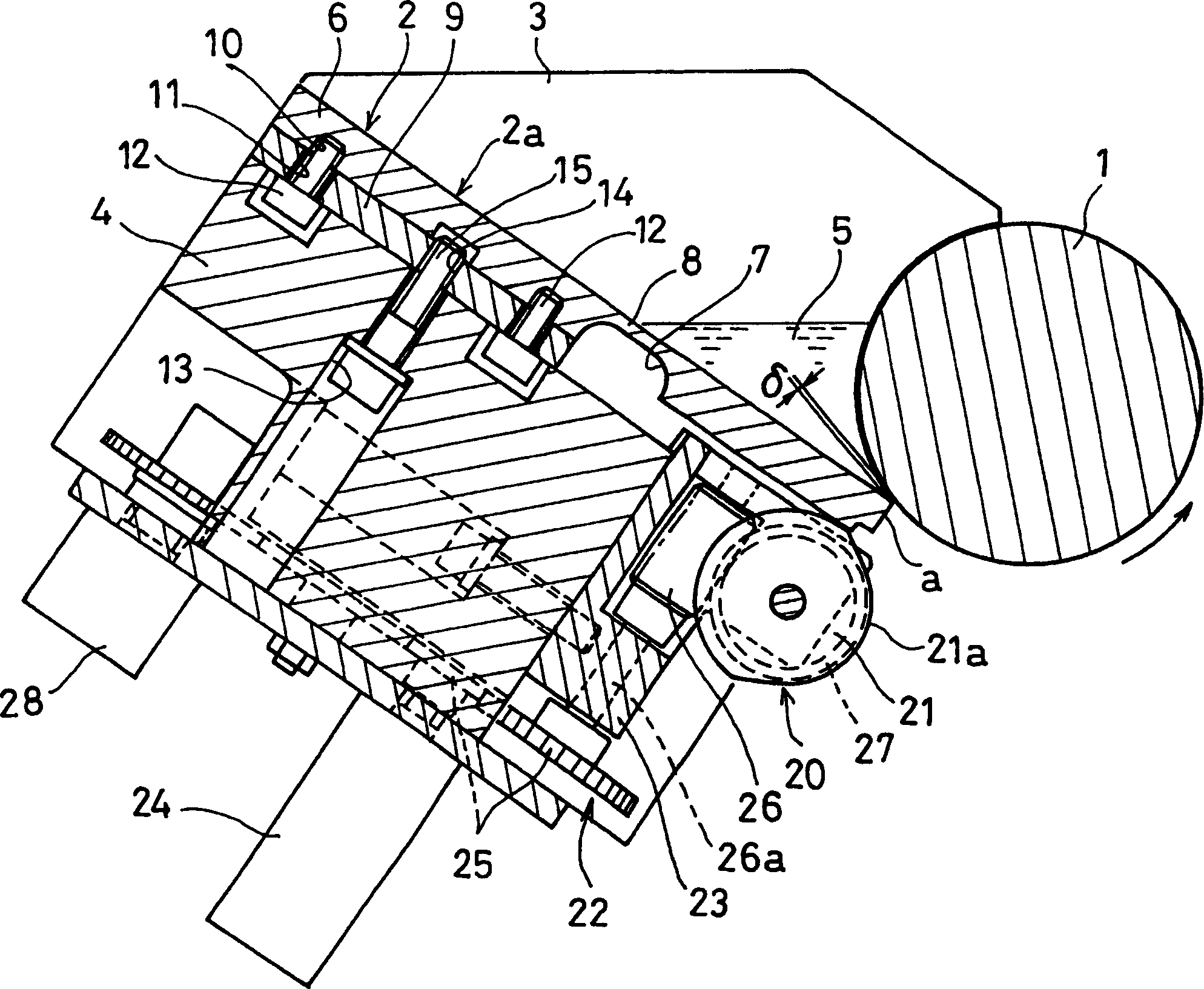
[0023] Below, according to Figure 1 ~ Figure 3 Embodiments of the present invention will be described. Such as figure 1 As shown, the lower part of the outer periphery of the ink fountain roller 1 rotating in the direction of the arrow in the figure is adjacent to the front end of the ink fountain scraper 2, and a gap δ is provided between the front end and the outer peripheral surface of the ink fountain roller 1.

[0024] The ink fountain scraper 2 is arranged in an inclined shape with the front end sloping downward, and a pair of baffles 3 are provided on both sides of the ink fountain scraper 2 . A pair of baffles 3 are attached to the support table 4 provided below, and the ink fountain 5 is installed on the ink fountain blade 2 by attaching the baffles 3 .

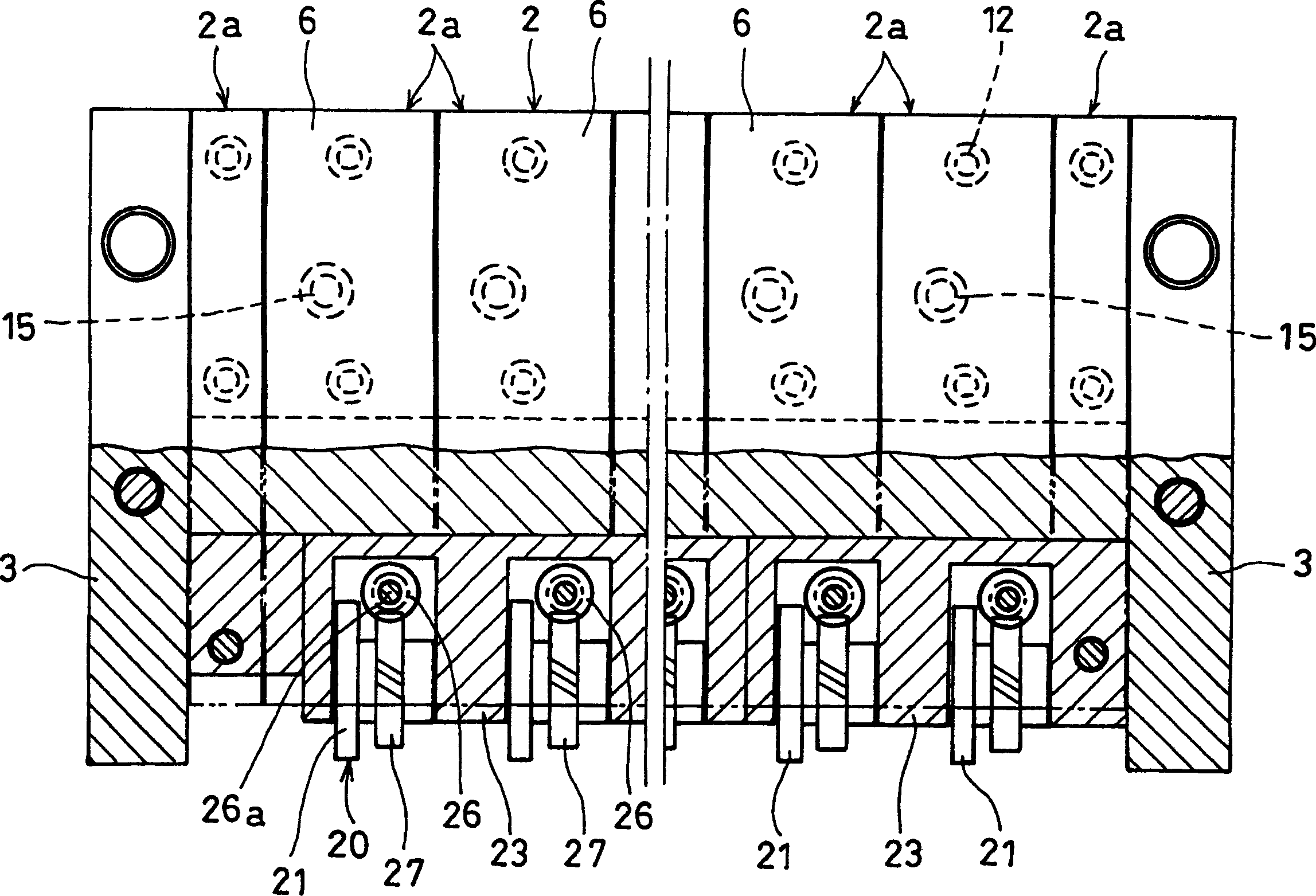
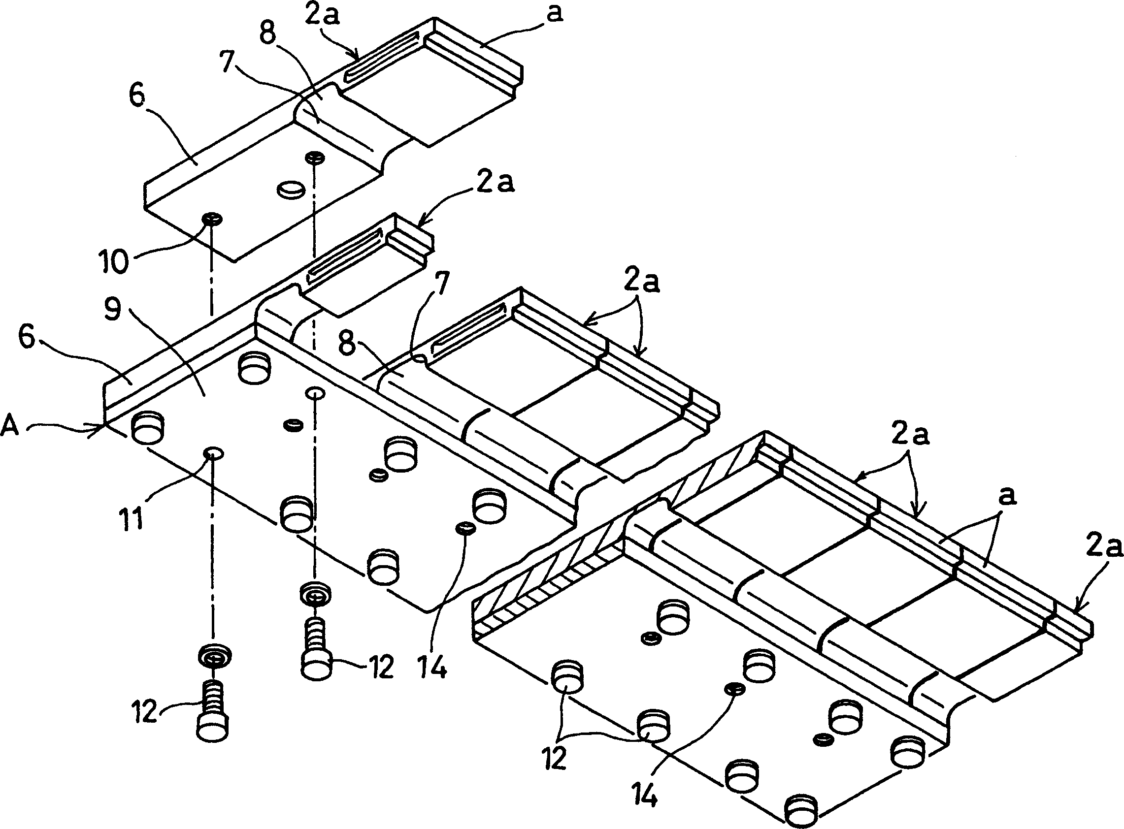
[0025] Such as figure 2 and image 3 As shown, the ink fountain scraper 2 is composed of a plurality of key bar scrapers 2a. The rear end of each key bar scraper 2a is a mounting portion 6, a groove 7 penetrat...


PUM


Abstract

To provide an ink quantity adjusting device for an inking unit, which can be easily assembled and can obtain a fountain blade excellent in the accuracy of an end surface.An end of the fountain blade 2, which is composed of a plurality of key blades 2a, is made to face a lower part of an outer periphery of a fountain roller 1. Back ends of the key blades 2a serve as mounting parts 6, and an elastically deformable thin-walled part 8 is provided on the front side of the mounting part 6. The key blades 2a are arranged in a juxtaposed manner by bringing side surfaces into close contact with one another, and the mounting parts 6 of the respective key blades 2a are screwed to a base 9, so that an assembly A can be formed. Before the assembly A is mounted on a supporting base 4, end surfaces of the key blades 2a are concurrently lapped so that the profile irregularity of the end surface of the fountain blade 2 can be improved. The assembly A is mounted on the supporting base 4 after the lapping of the end surfaces of the key blades 2a, so that the adjusting device can be easily assembled. (C)2004,JPO.

Description

technical field [0001] The invention relates to an ink supply adjusting device of an ink supply device in a printing machine. Background technique [0002] Generally, in the inking device of the printing press, the front end of the ink fountain scraper arranged obliquely at the lower part of the outer periphery of the fountain roller is arranged in a small gap, so that the outer periphery of the above-mentioned fountain roller rotating in one direction is adhered and formed on the The ink of the ink fountain on the ink fountain blade (fountain blade) is scraped off by the ink fountain blade at the same time, and the film thickness is uniformized. [0003] In addition, the ink on the ink fountain roller is transferred to the first roller in the roller row through the transfer roller, and the ink is evenly stirred by passing the ink from the first roller to the last roller in turn, so that the ink transferred to the last roller The ink on the plate is transferred from the ink...

Claims


Application Information

Patent Timeline
Patent Type & Authority Applications(China)
IPC IPC(8): B41F31/04
Inventor 石田好道大北坚一
Owner HAMADA PRINTING PRESS MFG
Why Eureka
Try Eureka